Wellbore motor having magnetic gear drive

a gear drive and gear drive technology, applied in the direction of machines/engines, positive displacement liquid engines, borehole/well accessories, etc., can solve the problems of reducing the operating life and reliability of in-wellbore systems, impractical use of such bits with rss systems, and impracticality of high-speed motors. , to achieve the effect of substantially preventing the rotation between the magnet section and the housing

Active Publication Date: 2009-06-23
MAGNOMATICS LTD
View PDF13 Cites 46 Cited by
  • Summary
  • Abstract
  • Description
  • Claims
  • Application Information

AI Technical Summary

Problems solved by technology

A limitation to RSS systems known in the art is that increased rotational speed of the drill string can reduce the operating life and in-wellbore reliability of such systems.
It is desirable, particularly with certain types of drill bits, to rotate the drill string at relatively high rates, thus making the use of such bits with RSS systems impractical.
One unavoidable aspect of using an electric motor in a wellbore to drive a pump is that it is necessary to seal the motor against intrusion of fluid from the wellbore.
The requirement to seal against the rotating shaft has made it impractical to use high speed motors in wellbores because high rotational speeds tend to limit seal life.
Reduction gear systems when operated in wellbore have a number of limitations.
First, it is necessary to provide a rotary seal somewhere in the system.
Pressure compensation devices known in the art may be subject to delays in compensation, causing fluid penetration into the interior of the device or fluid leakage.
The slight pressure differential has the effect of causing slow, but constant loss of the pressure compensating fluid.
Thus, even under ideal conditions the typical rotating seal device has a finite time that it can be used in a wellbore before removal to replenish the compensating fluid.
In the case of rotary devices using gears to multiply or reduce output speed relative to input speed, loss of lubrication can lead to gear failure.
Application of abrupt high torque has also been known to cause gear failure.
While the strength of the gears could otherwise be increased by increasing the size of the gears, such remedy is limited in the case of wellbore tools because such tools are typically limited in diameter to that of the wellbore being drilled less an annular space to allow cuttings and return mud flow to the Earth's surface.
In wellbore drilling generally, such abrupt torque application is frequent, because of the highly variable mechanical properties of the Earth formations being drilled and the relatively low resolution control over the amount of axial force applied to the drill bit on the typical drilling rig.
Planetary gears are generally limited to about 3¼ to 3½ to 1 input to output ratio because of the limitations of shaft and gear diameters, among other factors.
Such arrangement increases the overall length, weight, complexity and required lubrication reservoir capacity of the gear set.

Method used


Image

  • Wellbore motor having magnetic gear drive
  • Wellbore motor having magnetic gear drive
  • Wellbore motor having magnetic gear drive

Examples


Embodiment Construction

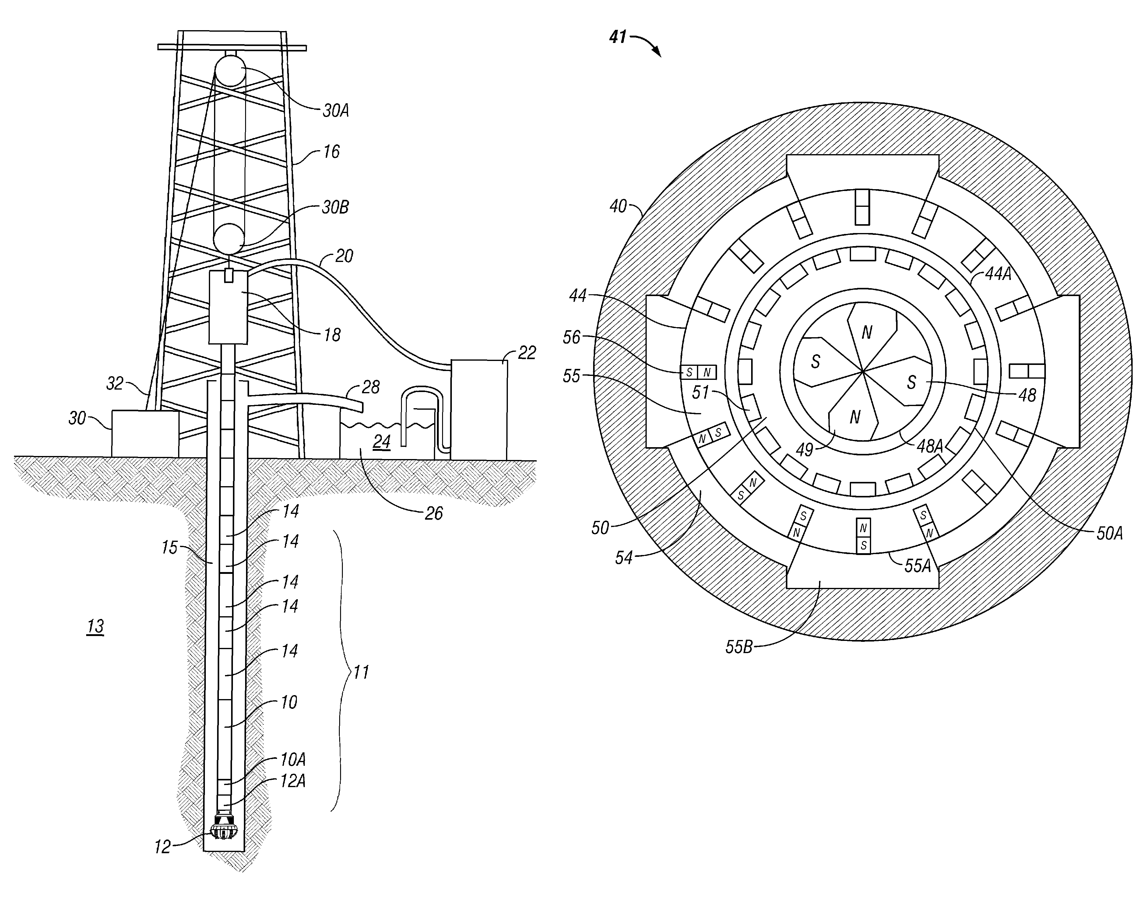
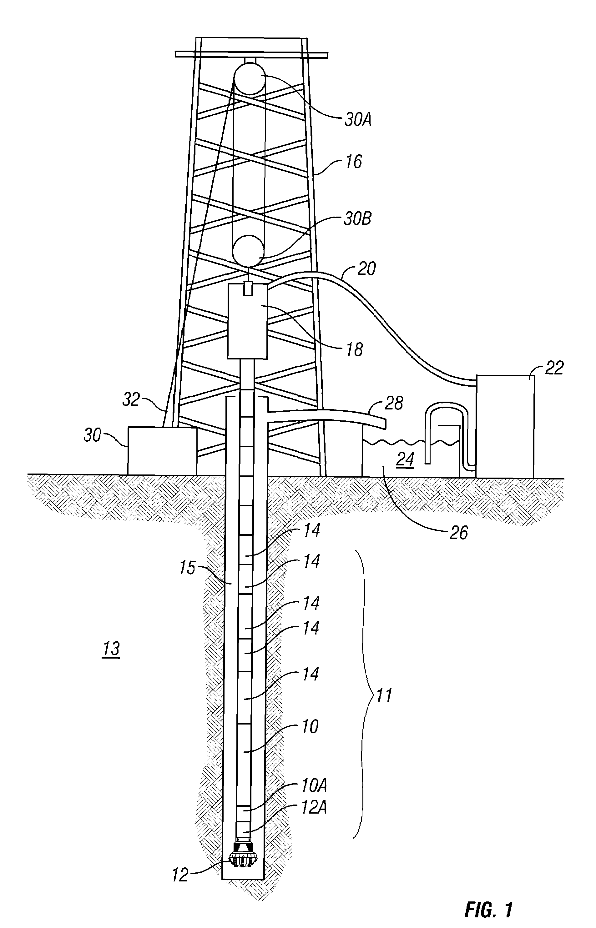
[0025]An aspect of the invention related to geared wellbore motors will first be explained in terms of a drilling motor that uses flow of drilling mud as an energy source. One implementation of a wellbore fluid-driven, geared motor according to the invention is shown in FIG. 1 as it would be used in a drill string for drilling a wellbore into the Earth. The drill string 11 includes segments of drill pipe 14 threadedly coupled end to end and suspended at the upper end thereof by a top drive 18. The top drive 18 is movably suspended within a derrick structure of a drilling rig 16. The drilling rig 16 includes a drill line 32 spooled by a winch called a “drawworks”30 to raise and lower the top drive 18 as required during drilling operations. The drill line 32 moves through a crown block 30A and a traveling block 30B having multiple sheaves thereon to raise and lower the top drive 18. The top drive 18 includes an electric or hydraulic motor (not shown separately) to turn the drill strin...


PUM


Abstract

A wellbore motor includes a source of rotational motive power disposed in a wellbore, a magnetic gear member operatively coupled at an input thereof to the source; and a magnetic gear member output coupled rotationally to a rotary wellbore tool.

Description

CROSS-REFERENCE TO RELATED APPLICATIONS[0001]This is a continuation in part of Ser. No. 11 / 604,660 filed on Nov. 27, 2006 now U.S. Pat. No. 7,481,283. Priority is claimed from U.S. Provisional Application No. 60 / 783,542 filed on Mar. 17, 2006.STATEMENT REGARDING FEDERALLY SPONSORED RESEARCH OR DEVELOPMENT[0002]Not applicable.BACKGROUND OF THE INVENTION[0003]1. Field of the Invention[0004]The invention relates generally to the field of rotary tools used in drilling and completion of wellbores in the Earth. More specifically, the invention relates to rotary tools that make use of geared couplings between a driven input shaft and a driving output shaft.[0005]2. Background Art[0006]Drilling and completion of wellbores in the Earth, such as are used in the production of petroleum from subsurface reservoirs, includes the use of a number of types of rotary tools. A particularly important one of such rotary tools is the so-called “rotary steerable directional drilling system” (RSS). RSS sys...

Claims


Application Information

Patent Timeline
Patent Type & Authority Patents(United States)
IPC IPC(8): E21B4/04E21B43/00
CPCE21B4/006H02K49/102
Inventor MCDONALD, WILLIAM J.PRICE, TIMOTHY F.HATCH, GARETH P.
Owner MAGNOMATICS LTD
Why Eureka
Try Eureka