Light source device and projector

a technology of light source device and projector, which is applied in the direction of fixed installation, lighting and heating equipment, television systems, etc., can solve the problems of impede the improvement of the utilization efficiency of light irradiated from the light source devi

Inactive Publication Date: 2009-06-23
SEIKO EPSON CORP
View PDF20 Cites 10 Cited by
  • Summary
  • Abstract
  • Description
  • Claims
  • Application Information

AI Technical Summary

Benefits of technology

[0009]An advantage of some aspects of the invention is to provide a light source device capable of prolonging a life of a light source lamp by reducing bias of temperature distribution of the light source lamp and avoiding a drop of illuminance and breakdown of the light source lamp in an arrangement in which a sub-reflection mirror is mounted to the light source lamp, and a projector using the same.
[0013]According to the aspect of invention, the heat insulating member is provided to at least a part of a light-emitting section of the light-emitting tube and a sealing section on the side opposite to a sealing section where the sub-reflection mirror is mounted out of the pair of sealing sections. Accordingly, heat of the side opposite to the side on which the sub-reflection mirror is mounted can be insulated by the heat insulating member in the light-emitting tube. Therefore, even when cooling is reinforced by forced cooling or the like to lower temperature of the light source lamp, it becomes possible to prevent the temperature of the side opposite to the side on which the sub-reflection mirror is mounted from dropping more than necessary, and to reduce a level of the bias of the temperature distribution of the light source lamp. Accordingly, it becomes possible to avoid a blackening phenomenon from occurring in the light source lamp, thereby prolong a life of the light source device.
[0019]According to the aspect of the invention, the heat insulating member is provided at the light-emitting section where the temperature becomes highest in the light-emitting tube. Therefore, the heat insulating member can effectively insulate the heat of the side opposite to the side on which the sub-reflection mirror is mounted in the light-emitting tube and can effectively suppress the reduction of temperature on the side opposite to the side on which the sub-reflection mirror is mounted even when cooling is reinforced by forced cooling or the like.
[0021]According to the aspect of the invention, the heat insulating member absorbs the incident light beam and the radiation heat. Accordingly, at a position to which the light beam irradiated from the light-emitting section is irradiated and the radiation heat is radiated (e.g., on a surface of the light-emitting section), the temperature of the heat insulating member becomes high by absorbing the irradiated light beam and the radiation heat, thereby reducing an amount of heat transferred from the light-emitting tube to the heat insulating member. Therefore, it becomes possible to more effectively suppress the temperature drop of the side opposite to the side on which the sub-reflection mirror is mounted in the light-emitting tube.
[0023]According to the aspect of the invention, the heat insulating member has a thermal conductivity smaller than a thermal conductivity of the light-emitting tube, which can effectively keep high temperature of a region where the heat insulating member is provided on the surface of the light-emitting tube. Therefore, even when cooling is reinforced by forced cooling or the like in the light-emitting tube, the temperature drop of the side opposite to the side on which the sub-reflection mirror is mounted can be effectively suppressed.
[0025]According to the aspect of the invention, since the projector has the light source device described above, the same advantages and effects as the light source device can be attained.

Problems solved by technology

When cooling is reinforced by forced cooling or the like to lower the temperature of the light source lamp, temperature of the side opposite to the side on which the sub-reflection mirror is mounted may lowered more than necessary and may cause a so-called blackening phenomenon by which an evaporated electrode material adheres to an inner wall of the light source lamp (a light-emitting tube).
Incidentally, when the heat insulating member is provided to the light-emitting tube so as to satisfy the relationship of θ1>θ2 that does not satisfy the relationship of θ1≦θ2 described above, the utilized light of the light beam irradiated from the light-emitting section is blocked by the heat insulating member, which may impede improvement of utilization efficiency of the light irradiated from the light source device.

Method used


Image

  • Light source device and projector
  • Light source device and projector
  • Light source device and projector

Examples


Embodiment Construction

)

[0030]An exemplary embodiment of the invention will be described below with reference to the drawings.

[0031]Arrangement of Projector

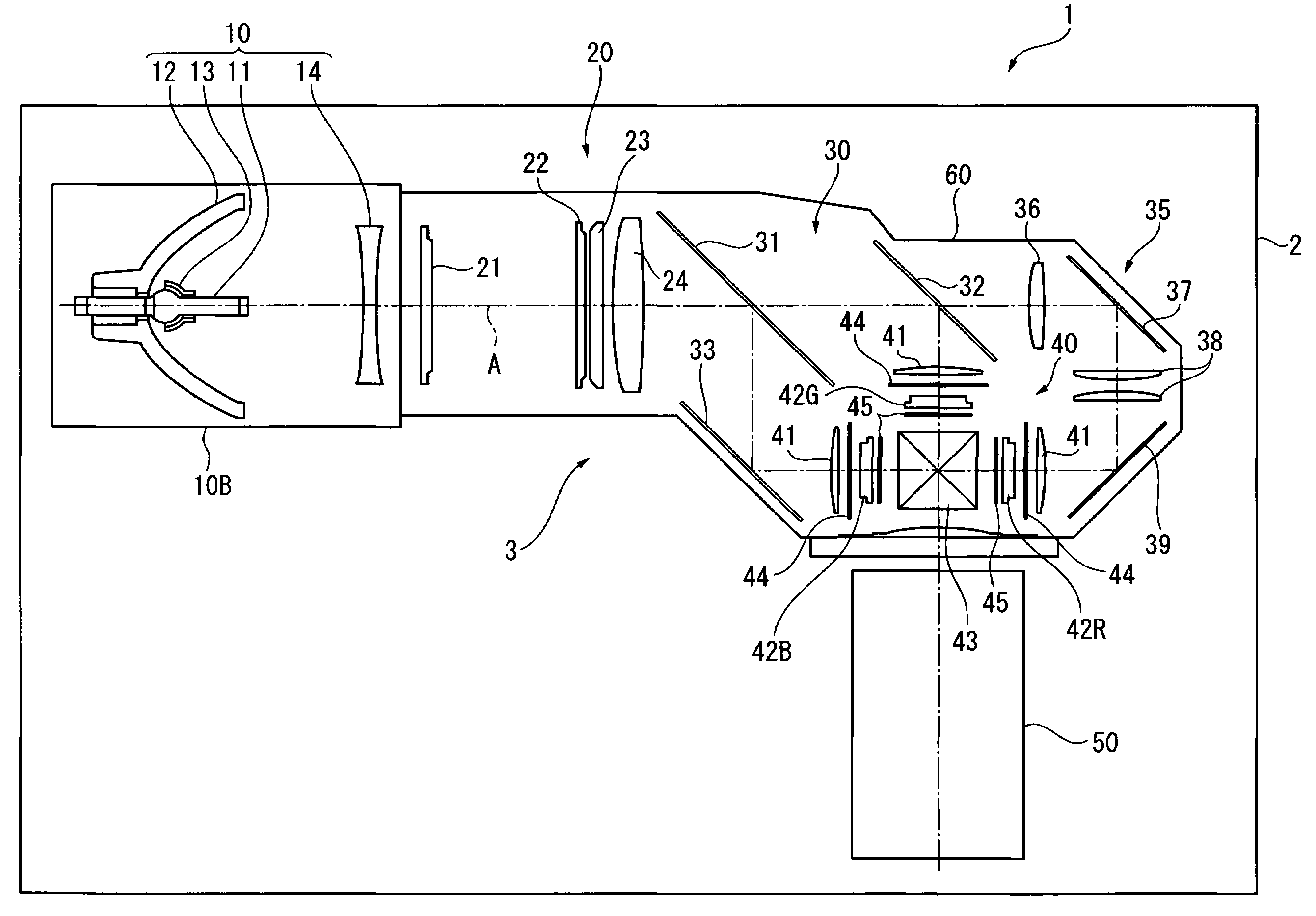
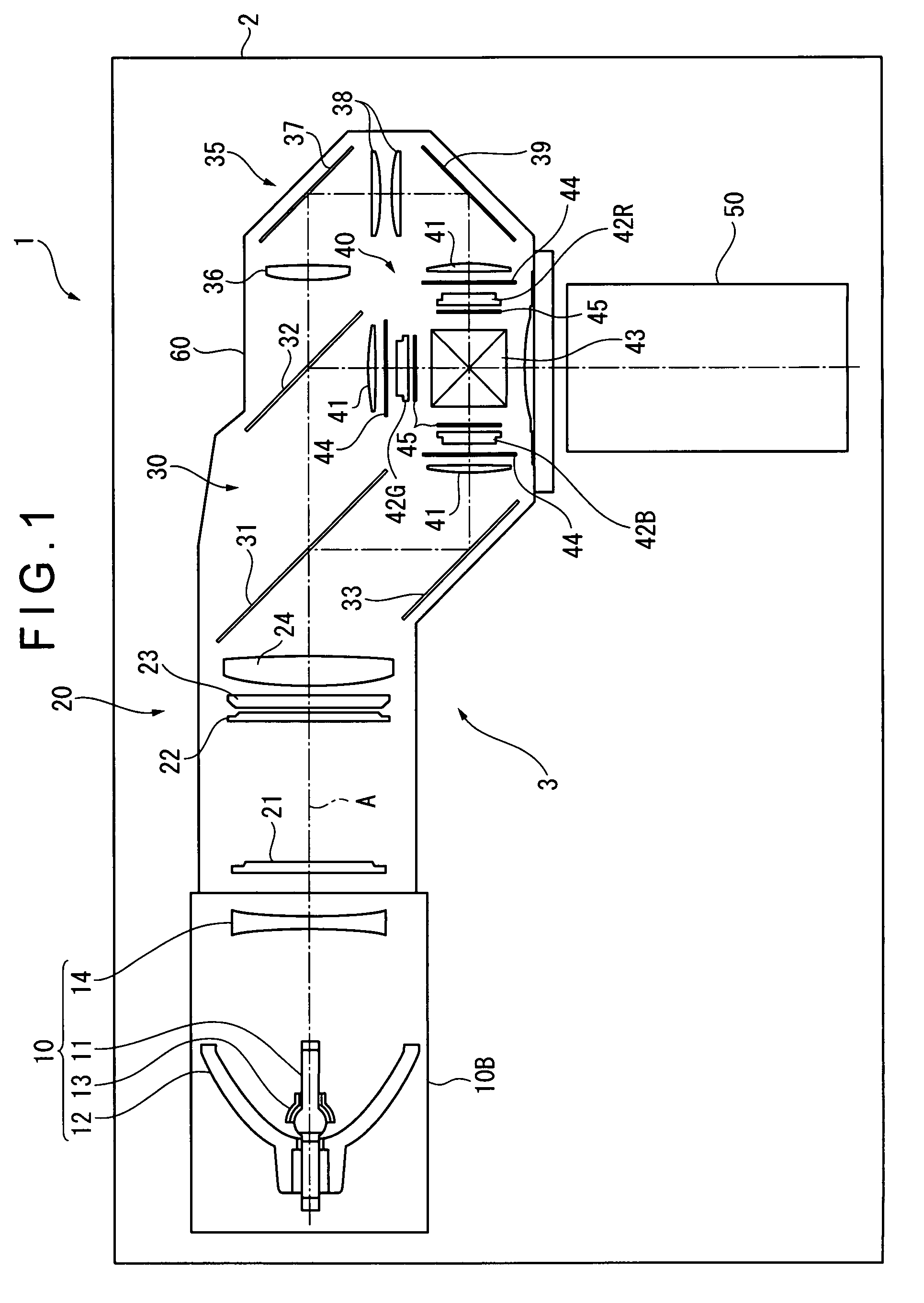
[0032]FIG. 1 is a plan view showing an outline of a projector 1 according to an exemplary embodiment of the invention.

[0033]The projector 1 is an optical apparatus for modulating a light beam irradiated from a light source in accordance with image information to form an image light and projecting the image light onto a projection plane such as a screen in an enlarged manner. As shown in FIG. 1, the projector 1 includes an exterior casing 2 having approximately a rectangular parallelepiped shape and an optical unit 3 stored in the exterior casing 2.

[0034]It should be noted that the exterior casing 2 is provided with a power unit for supplying electricity from the outside to the components of the projector 1, a cooling unit for cooling the inside of the projector 1, a controller for controlling the whole projector 1, and the like (each not shown) in addi...


PUM


Abstract

A light source device includes: a light source lamp having a light-emitting tube with a discharge space and a pair of electrodes disposed in the discharge space of the light-emitting tube; a reflector extending in a substantially concave shape in section, the reflector reflecting a light beam irradiated from the light source lamp; and a sub-reflection mirror having a reflection surface that is disposed to face a reflection surface of the reflector, the sub-reflection mirror reflecting a part of the light beam irradiated from the light source lamp toward the discharge space. The light-emitting tube has a light-emitting section having the discharge space therein and sealing sections provided on both sides of the light-emitting section. The sub-reflection mirror is formed in a shape of a bowl that covers the light-emitting section of the light-emitting tube, the sub-reflection mirror having an opening for mounting the sub-reflection mirror to the light-emitting tube by allowing one of the sealing sections of the light-emitting tube to be inserted thereinto. A heat insulating member is provided to at least a part of the light-emitting section and the other one of the sealing sections of the light-emitting tube.

Description

[0001]The entire disclosure of Japanese Patent Application No. 2006-038621, filed Feb. 15, 2006, is expressly incorporated by reference herein.BACKGROUND[0002]1. Technical Field[0003]The present invention relates to a light source device and a projector.[0004]2. Related Art[0005]There has been used a projector for modulating a light beam irradiated from a light source in accordance with image information to and project an optical image in an enlarged manner.[0006]As a light source device of the projector as described above, there has also been known a arrangement having a discharge type light source lamp such as a metal halide lamp and a high pressure mercury lamp, a reflector for reflecting a light beam irradiated from the light source lamp, and a sub-reflection mirror for reflecting the light beam irradiated forward from the light source lamp toward a side of the reflector (see, for instance, Document: JP-A-2005-148293).[0007]Meanwhile, when the sub-reflection mirror is mounted to...

Claims


Application Information

Patent Timeline
Patent Type & Authority Patents(United States)
IPC IPC(8): H01J61/35F21Y101/00
CPCF21V7/0025H01J61/045H01J61/86H04N5/7441
Inventor YAMAUCHI, KENTAROHASHIZUME, TOSHIAKI
Owner SEIKO EPSON CORP
Why Eureka
Try Eureka