
Flight path-driven mitigation of wavefront curvature effects in SAR images

a technology of sar images and flight paths, applied in the field of sar image mitigation, can solve the problems of large scenes with relatively coarse resolutions that exhibit artifacts, small scenes at finer resolutions that suffer more from range migration effects, and image formation is typically computationally intensiv

Active Publication Date: 2009-06-23
NAT TECH & ENG SOLUTIONS OF SANDIA LLC
View PDF12 Cites 18 Cited by
  • Summary
  • Abstract
  • Description
  • Claims
  • Application Information

AI Technical Summary

Benefits of technology

The patent text describes a technique for improving the quality of synthetic aperture radar (SAR) images by mitigating the effects of wavefront curvature. This technique involves using a polar format algorithm (PFA) to form the image, but residual effects of wavefront curvature can cause distortion and degradation of image quality. The patent proposes a method for reducing these effects without imposing limitations on the flight path of the SAR system. The technique involves analyzing the scene geometry and using a spatially variant filter to compensate for the residual video phase error. This method can be applied to both already-formed and future operational SAR systems.

Problems solved by technology

Image formation is typically a computationally intensive operation.
Large scenes with relatively coarse resolutions tend to exhibit artifacts resulting from approximations to the spherical wavefronts.
Small scenes at finer resolutions suffer more from range migration effects.
Although the resampling operation of PFA mitigates the problematic range migration, residual effects of wavefront curvature still manifest themselves as spatially variant distortions and image quality degradation, generally worsening in the image with pixel distance from the scene center.
In fact, a threshold on tolerance for image degradation imposes a scene size limit for a focused SAR image.
The desire for future operational systems to operate with ever-larger images at ever-finer resolutions exacerbates this problem.
These techniques are implemented within image formation algorithms and are generally not suitable for application to an already processed image, unless the original image formation processing is first undone.
However, the technique is designed for a linear flight path, and therefore has correspondingly limited robustness over imaging geometry.

Method used


Image

  • Flight path-driven mitigation of wavefront curvature effects in SAR images
  • Flight path-driven mitigation of wavefront curvature effects in SAR images
  • Flight path-driven mitigation of wavefront curvature effects in SAR images

Examples


Embodiment Construction

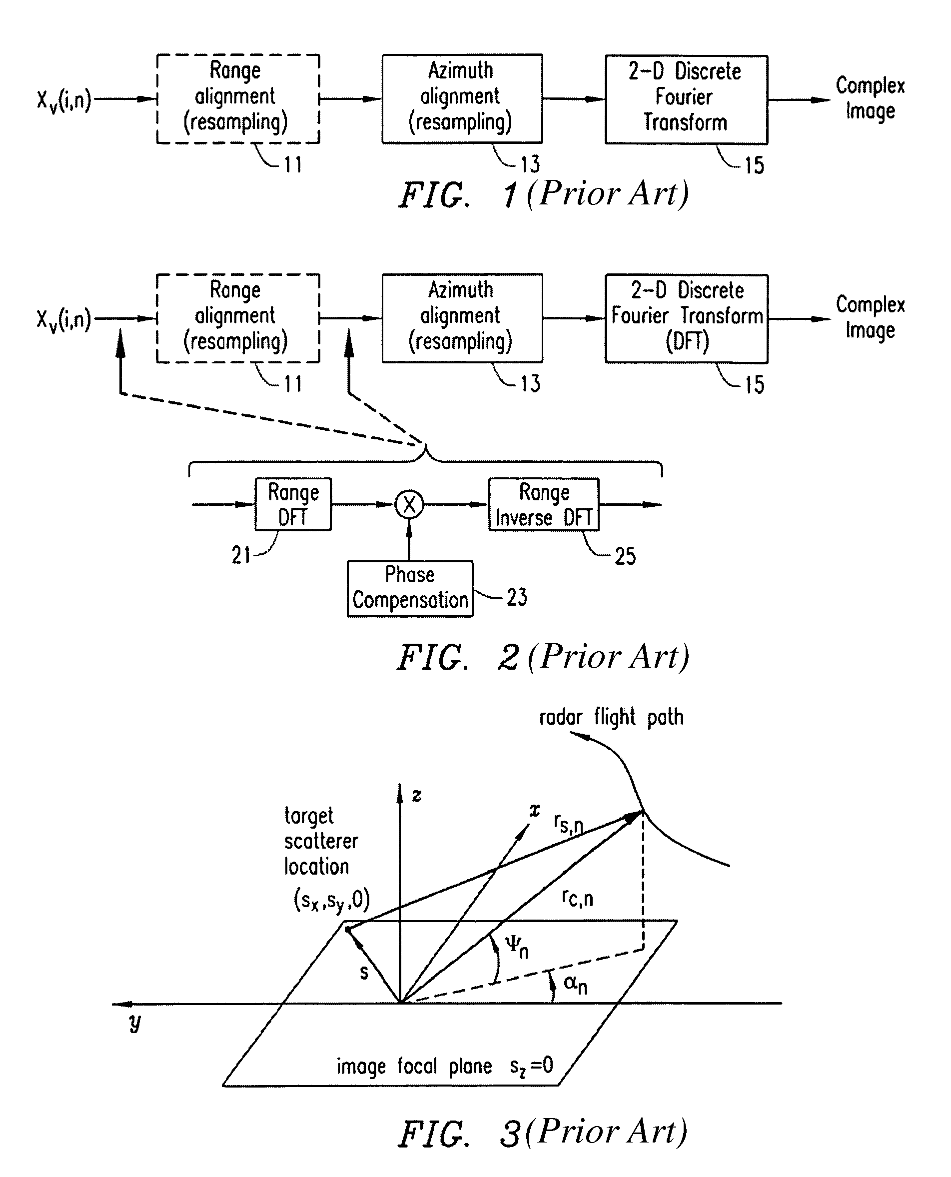
[0020]Consider a conventional LFM transmitted signal of the form

[0021]XT⁡(t,n)=AT⁢rect⁡(t-tnT)⁢exp⁢⁢j⁢{ϕT,n+ωT,n⁡(t-tn)+γT,n2⁢(t-tn)2}(1)

where

[0022]AT=the amplitude of the transmitted pulse,

[0023]t=time,

[0024]n=index value of pulse number, −N / 2≦n≦N / 2,

[0025]tn=reference time of nth pulse,

[0026]T=transmitted pulse width,

[0027]φT,n=transmit waveform reference phase of nth pulse,

[0028]ωT,n=transmit waveform reference frequency of nth pulse, and

[0029]γT,n=transmit waveform chirp rate of nth pulse. (2)

The received echo from a point scatterer is a delayed and attenuated version of this, namely

[0030]XR⁡(t,n)=ARAT⁢XT⁡(t-ts,n,n)(3)

where

[0031]AR=the amplitude of the received pulse,

[0032]ts,n=echo delay time of the received echo for the nth pulse. (4)

This is expanded to

[0033]XR⁡(t,n)=AR⁢rect⁡(t-tn-ts,nT)⁢exp⁢⁢j⁢{ϕT,n+ωT,n⁡(t-tn-ts,n)+γT,n2⁢(t-tn-ts,n)2}.(5)

The use of conventional stretch processing and Quadrature demodulation requires mixing XR with a Local Oscillator (LO) signal of the form

[00...


PUM


Abstract

A wavefront curvature effect associated with a complex image produced by a synthetic aperture radar (SAR) can be mitigated based on which of a plurality of possible flight paths is taken by the SAR when capturing the image. The mitigation can be performed differently for different ones of the flight paths.

Description

[0001]This invention was developed under Contract DE-AC04-94AL85000 between Sandia Corporation and the U.S. Department of Energy. The U.S. Government has certain rights in this invention.FIELD OF THE INVENTION[0002]The invention relates generally to synthetic aperture radar (SAR) and, more particularly, to mitigation of a wavefront curvature effect in a complex image produced using SAR techniques.BACKGROUND OF THE INVENTION[0003]Synthetic aperture radar (SAR) is a technique whereby multiple pulses from a moving radar are coherently combined to form an image while achieving an azimuth resolution much finer than the beamwidth of the radar's real antenna. Range resolution is a function of radar signal bandwidth. Image formation is typically a computationally intensive operation. SAR design consequently favors transform techniques that ultimately only approximate the matched filter for each pixel location in the image. The approximations tend to be most accurate at the image focal point...

Claims


Application Information

Patent Timeline
Patent Type & Authority Patents(United States)
IPC IPC(8): G01S13/90
CPCG01S13/9035G01S13/9019G01S13/904
Inventor DOERRY, ARMIN W.
Owner NAT TECH & ENG SOLUTIONS OF SANDIA LLC
Learn More