Montgomery modular multiplier and method thereof

a modular multiplier and multiplier technology, applied in the field of cryptosystems, can solve the problems of increasing computational speeds, affecting the integrity and secrecy of data, and limiting speed performance, so as to accelerate the speed of montgomery modular multiplication and reduce power consumption

a modular multiplier and multiplier technology, applied in the field of cryptosystems, can solve the problems of increasing computational speeds, affecting the integrity and secrecy of data, and limiting speed performance, so as to accelerate the speed of montgomery modular multiplication and reduce power consumption

US7552163B2Active Publication Date: 2009-06-23SAMSUNG ELECTRONICS CO LTD

Image

  • Montgomery modular multiplier and method thereof
  • Montgomery modular multiplier and method thereof
  • Montgomery modular multiplier and method thereof

Examples


Embodiment Construction

[0042]The following description of exemplary embodiment(s) is merely illustrative in nature and is in no way intended to limit the invention, its application, or uses.

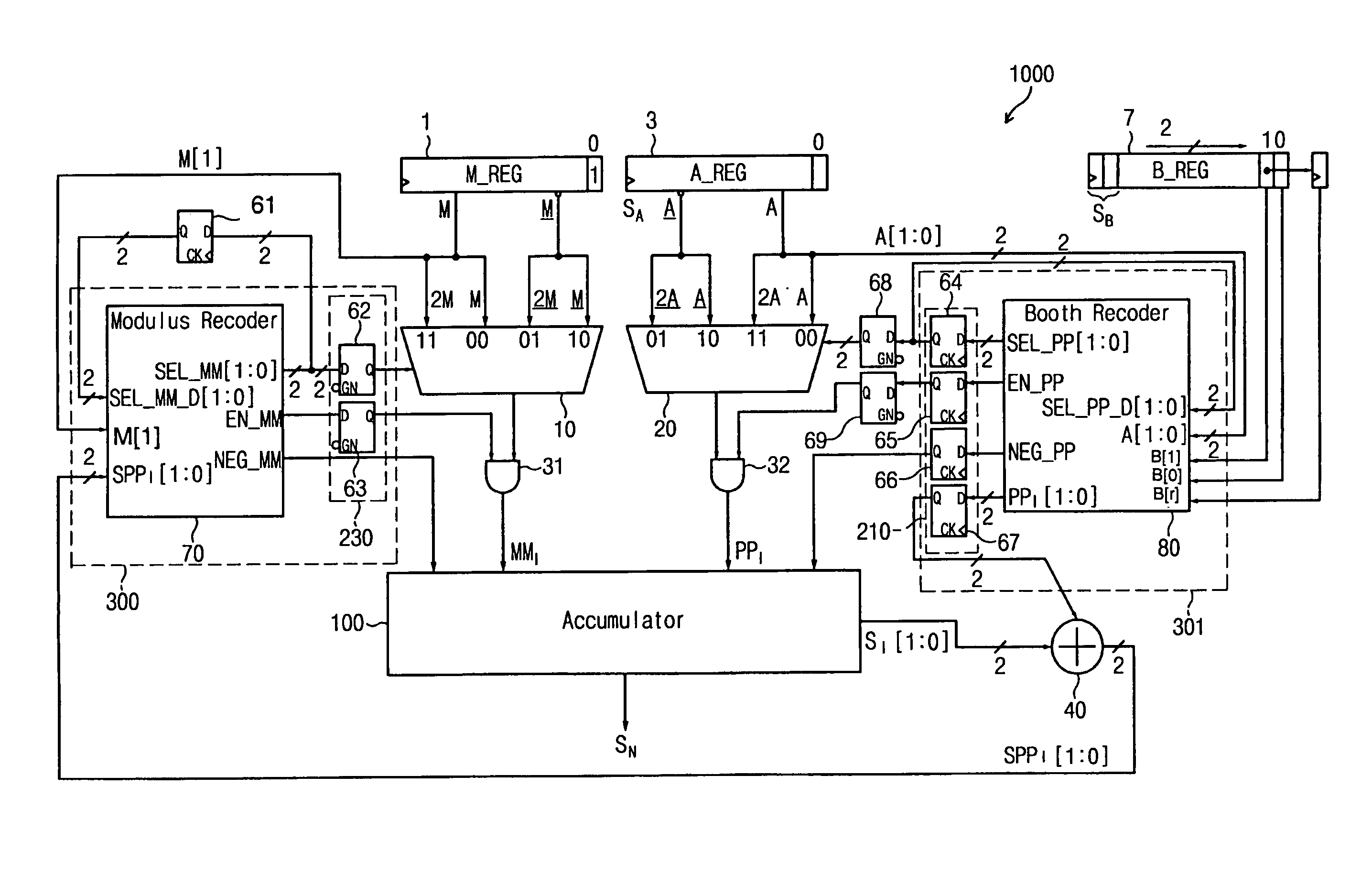
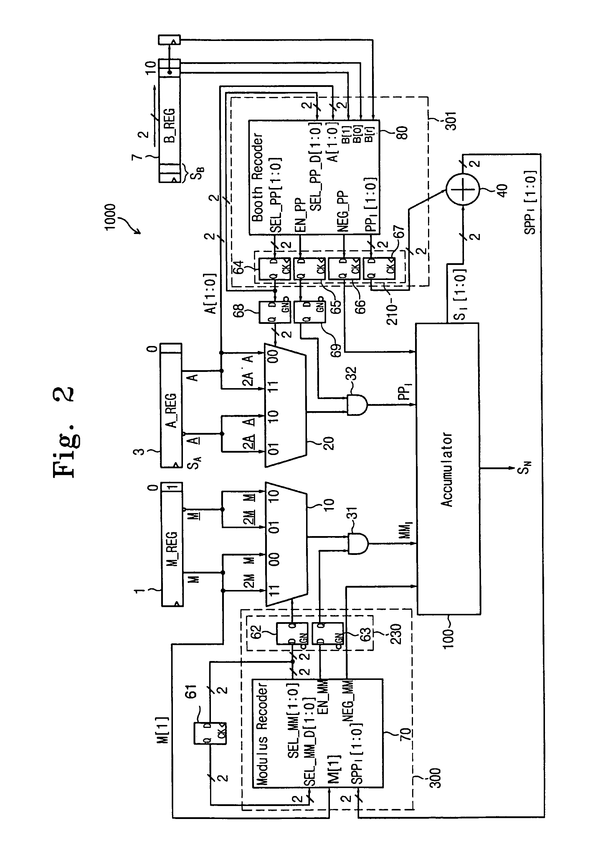
[0043]FIG. 2 illustrates a modular multiplier 1000 of an exemplary embodiment of the present invention. The multiplier 1000 can include a modulus (M) stored in a register 1, a multiplicand (A) stored in a register 3, a multiplicator (B) stored in a register 7, a Booth processor 301, a Modulus processor 300, a multiplexer (MUX) 10 aiding in the computation of the multiple modulus MMI, a MUX 20 aiding in the computation of the partial product PPI, and an accumulator 100 for aiding in the computation of the modular multiplication. The accumulator 100 inputs a partial product value PPI and the multiple modulus value MMI and produces a result for the Montgomery multiplier. In exemplary embodiments of the present invention, the positive value M can have n bits (M[nāˆ’1:0]). The positive or negative value A can have n+1 bits (A...


PUM


Abstract

A method for power reduction and increasing computation speed for a Montgomery modulus multiplication module for performing modulus multiplication. A coding scheme reduces the hamming distance for partial product and multiple modulus selection, reducing MUX operations and power consumption. Synchronization registers synchronize partial product and multiple modulus values input to an accumulator reducing glitch and / or increase computation speed. Registers provide storage of previous values and reduce the need to obtain the values from a MUX, reducing MUX operations and / or reducing power consumption.

Description

CROSS-REFERENCE TO RELATED APPLICATIONS[0001]The present application claims priority from a Korean application having Application No. P2003-29445, filed 9 May 2003 in Korea, the disclosure of which is incorporated herein in its entirety by reference.FIELD OF THE INVENTION[0002]The present invention relates to the field of cryptosystems and, more particularly, to a Montgomery modular multiplier.BACKGROUND OF THE INVENTION[0003]As the use of network systems grows, protection of network communications becomes more important. Protection of the integrity and secrecy of data becomes an issue.[0004]The basic process of code transporting, and decoding a message includes taking the message (plaintext), modifying (encrypting) the plaintext into ciphertext, transmitting the ciphertext to a receiver, and de-modifying (decrypting) the ciphertext, to recover the original message.[0005]In cryptosystems, an encryption key is used to encrypt the plaintext. The ciphertext is transmitted to a receiver...

Claims


Application Information

Patent Timeline
23 Jun 2009
Publication
US7552163B2
IPC
G06F7/00; G06F7/52
CPC
G06F7/00; G06F7/52; G06F7/728; G06F7/722; G06F2207/3884; G06F7/72
Inventors
SON, HEE KWAN