Multi-mode power amplifier with low gain variation over temperature

a technology of power amplifiers and temperature variations, applied in the field of power amplifiers, can solve the problems of reducing the power gain of the lower power amplifier and adding to the loss of power gain, and achieve the effects of increasing the dc current density, increasing the operating and/or junction temperature, and reducing the power gain of the power transistor

Active Publication Date: 2009-06-30
SEMICON COMPONENTS IND LLC
View PDF5 Cites 53 Cited by
  • Summary
  • Abstract
  • Description
  • Claims
  • Application Information

AI Technical Summary

Problems solved by technology

Therefore, the increase in DC collector current at rising temperature slightly increases the power gain of the higher power amplifier compensating somewhat for the loss of power gain due to rising temperature, while the decrease in DC collector current at rising temperature decreases the power gain of the lower power amplifier adding to the loss of power gain due to rising temperatures.

Method used


Image

  • Multi-mode power amplifier with low gain variation over temperature
  • Multi-mode power amplifier with low gain variation over temperature
  • Multi-mode power amplifier with low gain variation over temperature

Examples


example 1

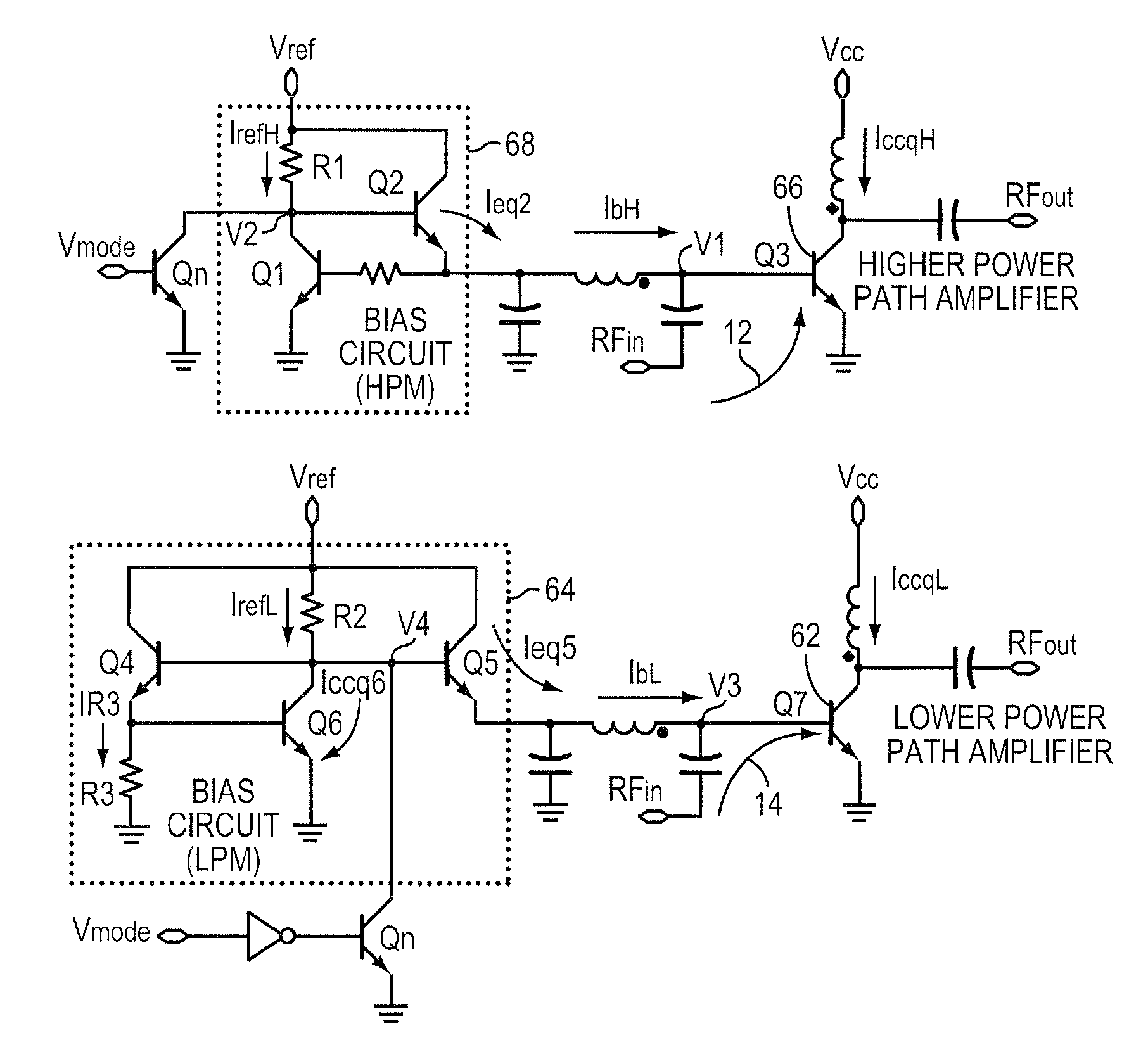
[0036]In FIG. 5, R1 is 330 ohms and Vref is 2.85V, the following applies:

[0037]

TEMPV1V2IrefHIeq2IbHIccqH25° C.1.25 V2.45 V1.25 mA170 uA166 uA30.0 mA85° C.1.19 V2.32 V1.66 mA360 uA348 uA39.5 mA

example 2

[0038]In FIG. 7, R2 is 1.1 Kohm, R3 is 2 kohm and Vref is 2.85V, the following applies:

[0039]

TEMPV3V4IrefLIeq5IR3Iccq6IbLIccqL25° C.1.252.45365166609360166 uA  30 mAVVuAuAuAuA85° C.1.172.29508240511500240 uA24.6 mAVVuAuAuAuA

[0040]The above tables demonstrate that the output DC collector current for the higher power amplifier, IccqH, of FIG. 5 increases when temperature is raised, while the corresponding current for the lower power amplifier, IccqL, decreases when temperature is raised. Please note that the base current to the output transistor in each case rises with temperature, but that the rise in IbL is much reduced compared to the increase in IbH. In this instance the loss of DC current gain for Q7 with rising temperature dominates the increase in base current, IbL, resulting in a reduction in IccqL with temperature.

[0041]There are several approaches and alternatives to explaining the temperature response of the circuit in FIG. 5 compared to that in FIG. 7. Perhaps the best is ...


PUM


Abstract

A multi-mode RF amplifier is described having at least a higher and a lower power path coupling an input to an output. At a pre-selected output power level, the higher power path is enabled while the lower power path is disabled when more output power is required. The process is reversed when less power is needed. The present invention matches the power gain variation over temperature characteristic of each path such that, especially at the cross over point, the gain delta (the difference in power gain between the two paths) has minimal variation over temperature. Such power gain characteristic is required for meeting the test requirements, specifically the inner loop power control, for third generation (3G) cellular handsets.

Description

[0001]The present application is related to the commonly owned U.S. Pat. No. 7,157,966 entitled, “Multi-Mode Power Amplifier.” This prior application is hereby included herein by reference.BACKGROUND OF THE INVENTION[0002]1. Field of the Invention[0003]The present invention relates to power amplifiers and more particularly to power amplifiers in battery powered handsets, and even more particularly to such power amplifiers exhibiting two or more power paths.[0004]2. Background Information[0005]Radio-frequency (RF) signals generated at a mobile handset generally are amplified, transmitted through the handset antenna and sent to a base station for distribution to receivers. Often the frequency bands of operation of the handsets are predetermined, mainly in the frequency range from 800 MHz to 2000 MHz for various mobile standards such as WCDMA (wide band code division multiple access) and CDMA (code division multiple access). The present invention, however, may find advantageous use in ...

Claims


Application Information

Patent Timeline
Patent Type & Authority Patents(United States)
IPC IPC(8): H03F3/04
CPCH03F1/0261H03F1/0277H03F1/30H03F3/19H03F3/72H03F2200/18H03F2200/411H03F2200/447H03F2200/451H03F2203/7231H03F2203/7236
Inventor HAU, GARYTURPEL, JEFFREY R.
Owner SEMICON COMPONENTS IND LLC
Why Eureka
Try Eureka