Methods and systems for automated ply boundary and orientation inspection

a technology of ply boundary and orientation inspection, applied in the field of layered composite material fabrication, can solve the problems of inability to project at the required accuracy over an enlarged surface, inhibit the rate capability of a production facility, and not be acceptable in a manufacturing environmen

Active Publication Date: 2009-06-30
THE BOEING CO
View PDF37 Cites 132 Cited by
  • Summary
  • Abstract
  • Description
  • Claims
  • Application Information

AI Technical Summary

Problems solved by technology

While this may be acceptable in a prototyping environment, it is not acceptable in a manufacturing environment.
In an increased production rate environment, the task of inspecting ply boundaries utilizing the OLT process greatly inhibits the rate capabilities of a production facility.
In addition, as the composite structures may be modified, for example, a stretched version of the composite fuselage, the OLTs may not have the capability to project at a needed accuracy over an enlarged surface.
When working with a large structure, such as the full surface of a fuselage barrel, an angle of incidence issue arises.
Specifically, due to a limitation on the angle of incidence between the laser projection and the part surface, a full fuselage ply must be projected onto in multiple (e.g., at least six) segments of the OLT to cover the full circumference of the fuselage.
As mentioned above, the current OLT process is time consuming.
On average, thirty or more hours are attributed to inspection of ply boundary and orientation for a full fuselage part, which is unacceptable in a high rate of production environment.
In addition to the throughput rate limitations of the current OLT system, there are some technical limitations as well, such as the angle of incidence problem described above.
Currently, there is no more acceptable and cost effective process for inspecting ply boundaries than OLT.

Method used


Image

  • Methods and systems for automated ply boundary and orientation inspection
  • Methods and systems for automated ply boundary and orientation inspection
  • Methods and systems for automated ply boundary and orientation inspection

Examples


Embodiment Construction

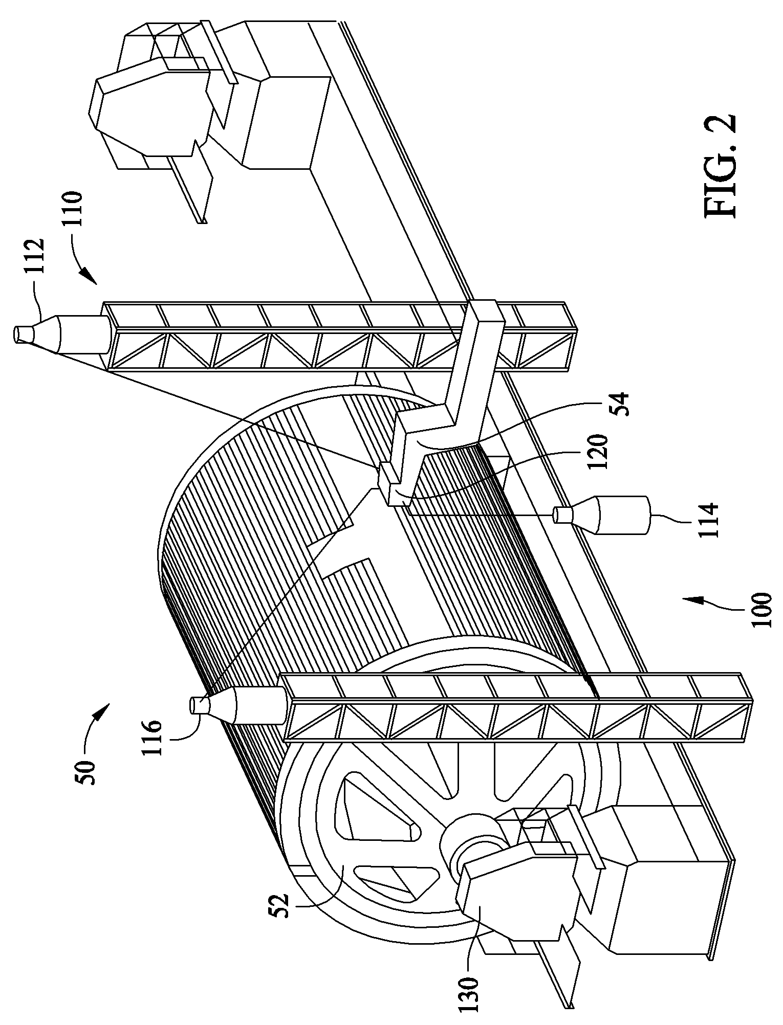
[0012]To address the above described issues with ply boundary and orientation inspection, embodiments of the described methods and systems are utilized to increase rate capability, reduce recurring flow time, reduce labor hours, and enable ply inspection on future versions and variations of the composite structure, which in a particular embodiment, is a composite component for a fuselage barrel.

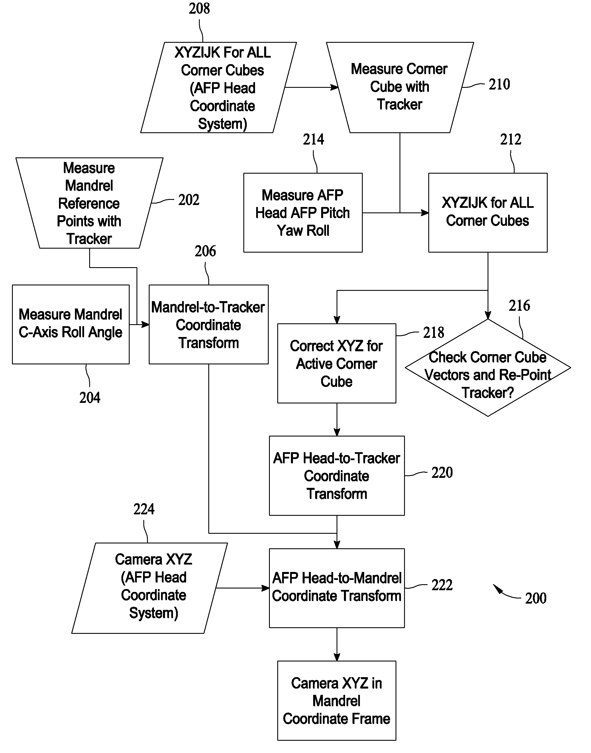
[0013]The described embodiments utilize a vision system, combined with laser tracker measurement devices, or other position measuring devices, and encoders, to map where carbon fiber material is being placed on a cure mandrel (or tool) by automated fiber placement machines. More specifically, the system records where the material is being placed onto the tool and compares it against the nominal material placement engineering data set in order to indicate areas of placement that are outside of manufacturing tolerances.

[0014]As described above, the current optical laser template (OLT) process i...


PUM

PropertyMeasurementUnit
angleaaaaaaaaaa
receiving distancesaaaaaaaaaa
distancesaaaaaaaaaa

Abstract

A method for determining the positional laydown accuracy of an automated lamination machine during fabrication of a multiple layered part is described. The method includes measuring a position of a placement head of the lamination machine in a coordinate system, determining a location of a ply edge with respect to the placement head, transforming the location of the ply edge into the coordinate system, based on the measured head position, transforming the location of the ply edge from the coordinate system into a second coordinate system that is associated with the part being fabricated, and comparing actual ply edge location in the second coordinate system to an expected ply edge location defined in the second coordinate system, the second coordinate system associated with the part being fabricated, to determine the laydown accuracy of the machine.

Description

BACKGROUND OF THE INVENTION[0001]This invention relates generally to fabrication of layered composite materials, and more specifically, to methods and systems for automated ply boundary and orientation inspection.[0002]In some current production situations, the fabricator is required to inspect 100 percent of the ply placements for a composite structure using optical laser templates (OLT). While it is possible to use other large scale metrology methods, such as laser radar, OLT is currently the most efficient method of inspection. With certain structures, this inspection process takes, on average, between thirty and ninety minutes per ply. These structures may include sixty to seventy or more individual plies. As is easily understood, this OLT inspection turns out to be a significant portion of the total flow time utilized in the fabrication of the structure, which in certain instances may be a composite fuselage barrel for an aircraft. While this may be acceptable in a prototyping ...

Claims


Application Information

Patent Timeline
Patent Type & Authority Patents(United States)
IPC IPC(8): G06F15/00B32B38/00
CPCB29C70/32B29C70/386B29K2707/04
Inventor BRENNAN, JOSEPH DANIELATSEBHA, SOLOMON T.DORSEY-PALMATEER, JOHN W.ANDERSON, PATRICK L.
Owner THE BOEING CO
Why Eureka
Try Eureka