Sidestream gas sampling system using a capillary tube flow sensor

Active Publication Date: 2009-07-07
PHILIPS RS NORTH AMERICA LLC
View PDF11 Cites 24 Cited by
  • Summary
  • Abstract
  • Description
  • Claims
  • Application Information

AI Technical Summary

Benefits of technology

[0013]The pressure drop across the capillary tube is used to determine the flow of gas, in particular, the flow of gas through the gas measurement site. A capillary tube for flow control is not substantially affected by altitude and the composition of the gas. It is also less prone to clogging, thereby reducing the need for costly preventive maintenance required by conventional orifice based sidestream gas monitoring systems.
[0014]Existing sidestream CO2 analyzers measure the pressure drop across an orifice to control the flow rate of the sampling system. The method of the invention measures the pressure drop across a capillary tube, which is not dependent on gas density, to control the sampling flow rate. The sidestream flow controller, according to the method of the invention, controls the sampling flow rate by measuring the pressure differential across a capillary tube. An advantage of this capillary-based flow control system is that it is only influenced by viscosity, which varies substantially less than density across the wide variety of gases, including anesthetic and therapeutic gases that may pass through the gas s

Problems solved by technology

Conventional sidestream systems clog easily and frustrate the user to

Method used


Image

  • Sidestream gas sampling system using a capillary tube flow sensor
  • Sidestream gas sampling system using a capillary tube flow sensor
  • Sidestream gas sampling system using a capillary tube flow sensor

Examples


Example

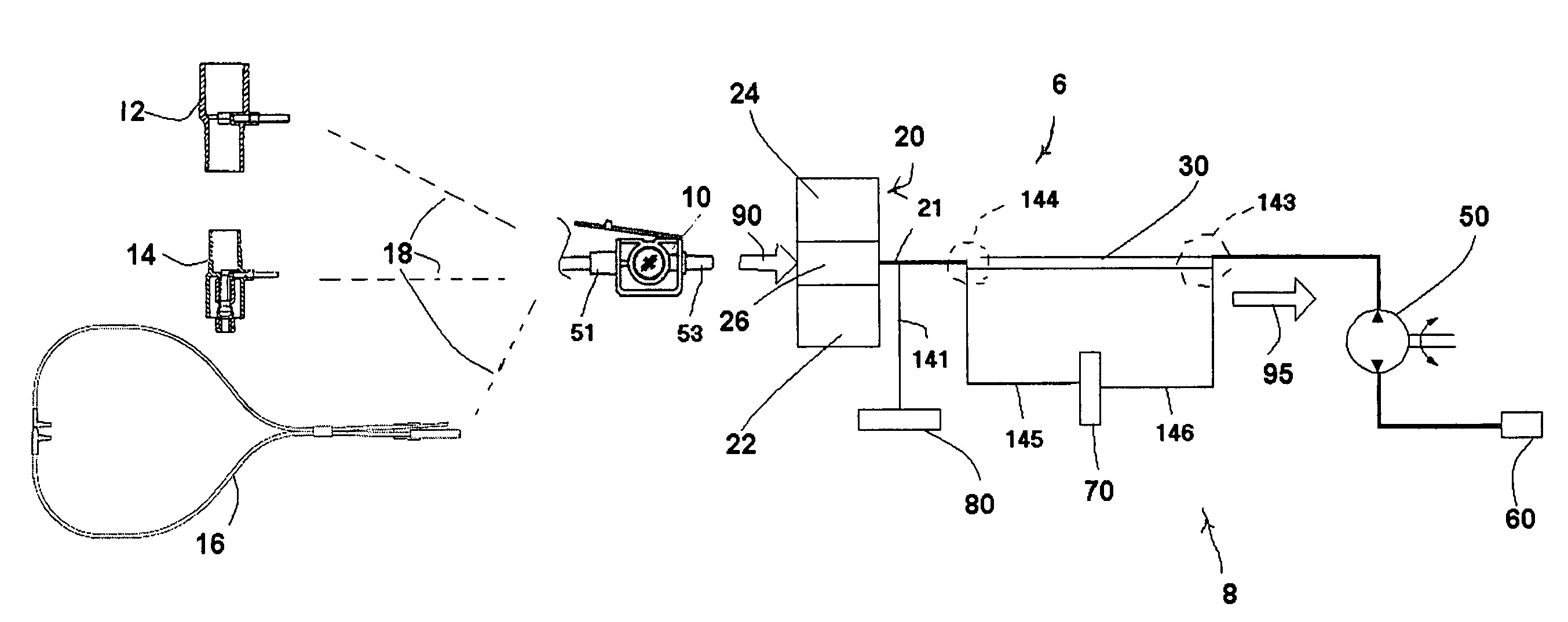
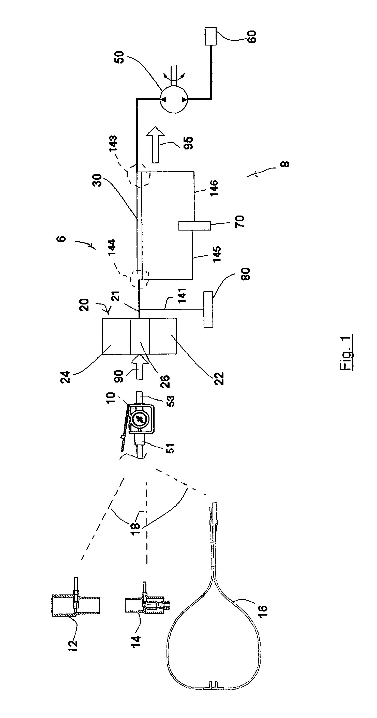
[0022]FIG. 1 is a high-level schematic diagram of a sidestream gas sampling system 6 according to the principles of the present invention. Sidestream gas sampling system 6 includes a flow monitoring / control system 8, which is discussed in greater detail below, and a gas measurement system 20. FIG. 1 also illustrates a variety of different patient interface devices suitable for use with the sidestream gas sampling system.

[0023]Sidestream gas sampling is used on both intubated and non-intubated patients ranging from neonates to adults. To accommodate these different applications, different patient interface devices must be used. FIG. 1 illustrates one set of patient interface devices that can be coupled to a common removable sample cell 10 via a conduit, indicated schematically at 18. An exemplary configuration for a sample cell that is suitable for use in the present sidestream gas sampling system is the subject of pending U.S. application Ser. No. 10 / 384,329, entitled “Sidestream Ga...


PUM


Abstract

A sidestream gas sampling system that includes a conduit that communicates a flow of gas to a gas measurement site. A gas measurement assembly measures a constituent of the flow of gas at the gas measurement site. A capillary tube communicates the flow of gas from the gas measurement site. A differential pressure transducer in fluid communication with first and second portions of the capillary tube measure a pressure differential between these two portions. A controller is coupled to the differential pressure transducer to measure the flow of gas based on the output of the differential pressure transducer and to control the flow of gas via a flow generator coupled to the gas flow path.

Description

BACKGROUND OF THE INVENTION[0001]1. Field of the Invention[0002]The present invention relates to a sidestream respiratory gas sampling system with flow based feedback control, and, in particular, such a sidestream sampling system that utilizes a pressure drop across a capillary tube to measure and control the sidestream flow.[0003]2. Description of the Related Art[0004]Gas analyzers are widely used in medical applications and are typically categorized into two different types: (1) “diverting” or “sidestream” gas sampling systems; and (2) “non-diverting” or “mainstream” gas sampling systems. A mainstream gas sampling system includes a sample cell that is disposed along the main path of a breathing circuit through which a patient's respiratory gases flow. As a result, the patient's inspired and expired respiratory gases pass through a sample cell, which is also known as a “cuvette”. A gas measurement system, which includes the elements necessary for monitoring respiratory gases, such ...

Claims


Application Information

Patent Timeline
IPC IPC(8): A61M16/00
CPCA61B5/0836A61M16/085A61B5/097A61M16/0833A61M16/0858
Inventor PIERRY, ANTHONY T
Owner PHILIPS RS NORTH AMERICA LLC
Why Eureka
Try Eureka