Fluid dynamic bearing device and motor equipped with the same

a technology of fluid dynamic bearing and bearing device, which is applied in the direction of sliding contact bearing, record information storage, instruments, etc., can solve the problems of unavoidable increase in machining cost, foreign matter generation, and insufficient cost advantage of resin cost, so as to enhance the bearing performance of fluid dynamic bearing device and reduce the production cost of the housing

Inactive Publication Date: 2009-07-07
NTN CORP +1
View PDF18 Cites 17 Cited by
  • Summary
  • Abstract
  • Description
  • Claims
  • Application Information

AI Technical Summary

Benefits of technology

[0010]It is an object of the present invention to achieve a reduction in the production cost of a fluid dynamic bearing device of this type, there by providing a less expensive fluid dynamic bearing device.
[0013]By forming the side portion, which constitutes the housing, of an injection molding of a resin material, it is possible to produce a housing of higher precision and less weight as compared with the case in which it is formed of metal by machining, such as cutting, or press working. Further, since the fixing portion formed in the side portion and used to fix the bottom member is a molding surface formed through solidification, in conformity with the inner surface of the mold, of the resin injected by the injection molding, it is possible to form a high precision fixing portion easily and at low cost. Since the fixing portion is a smooth surface where no filler in the resin material is exposed, there is generated no minute foreign matter or the like which leads to contamination through friction when press-fitting the bottom member.
[0014]The gate through which the resin material (molten resin) is injected into the mold (cavity) may be provided at a position in the cavity other than the position corresponding to the fixing portion. In particular, it is desirable for the gate to be provided at a position corresponding to the inner peripheral edge portion on the axially opposite side of the fixing portion. With this construction, it is possible to fill the cavity uniformly with resin, thereby making it possible to perform high precision component molding. In this process, a gate cut portion as a gate mark is formed on the inner peripheral edge portion at one end of the side portion. This portion, however, is not directly related to the fixation of other components, so there is no need to separately perform finishing or the like. Thus, it is possible to reduce the number of steps and to achieve a reduction in the production cost of the housing. Regarding the gate configuration, there are no particular limitations as long as it allows the cavity to be uniformly filled with molten resin. It may be selected from a group consisting of a film gate, a point gate (inclusive of a multi-point gate), a disc gate, etc.
[0017]In view of this, in the present invention, the gate cut portion is covered with an adhesive. This makes it possible to prevent falling of burrs, etc. by a simple measure, making it possible to solve the above problem at low cost.
[0021]As described above, according to the present invention, it is possible to achieve a reduction in the production cost of the housing, and to enhance the bearing performance of a fluid dynamic bearing device without involving a problem such as contamination.

Problems solved by technology

Thus, an increase in machining cost is unavoidable, which means the advantage in terms of cost attained by using resin cannot be enjoyed to a sufficient degree.
Further, there is a possibility of foreign matter generated as a result of machining remaining at the fixing portion.
In that case, such foreign matter may enter the interior of the bearing device after the press-fitting of the bottom member and constitute a contaminant, thereby deteriorating the bearing performance.

Method used


Image

  • Fluid dynamic bearing device and motor equipped with the same
  • Fluid dynamic bearing device and motor equipped with the same
  • Fluid dynamic bearing device and motor equipped with the same

Examples


Embodiment Construction

[0032]In the following, an embodiment of the present invention will be described with reference to the drawings.

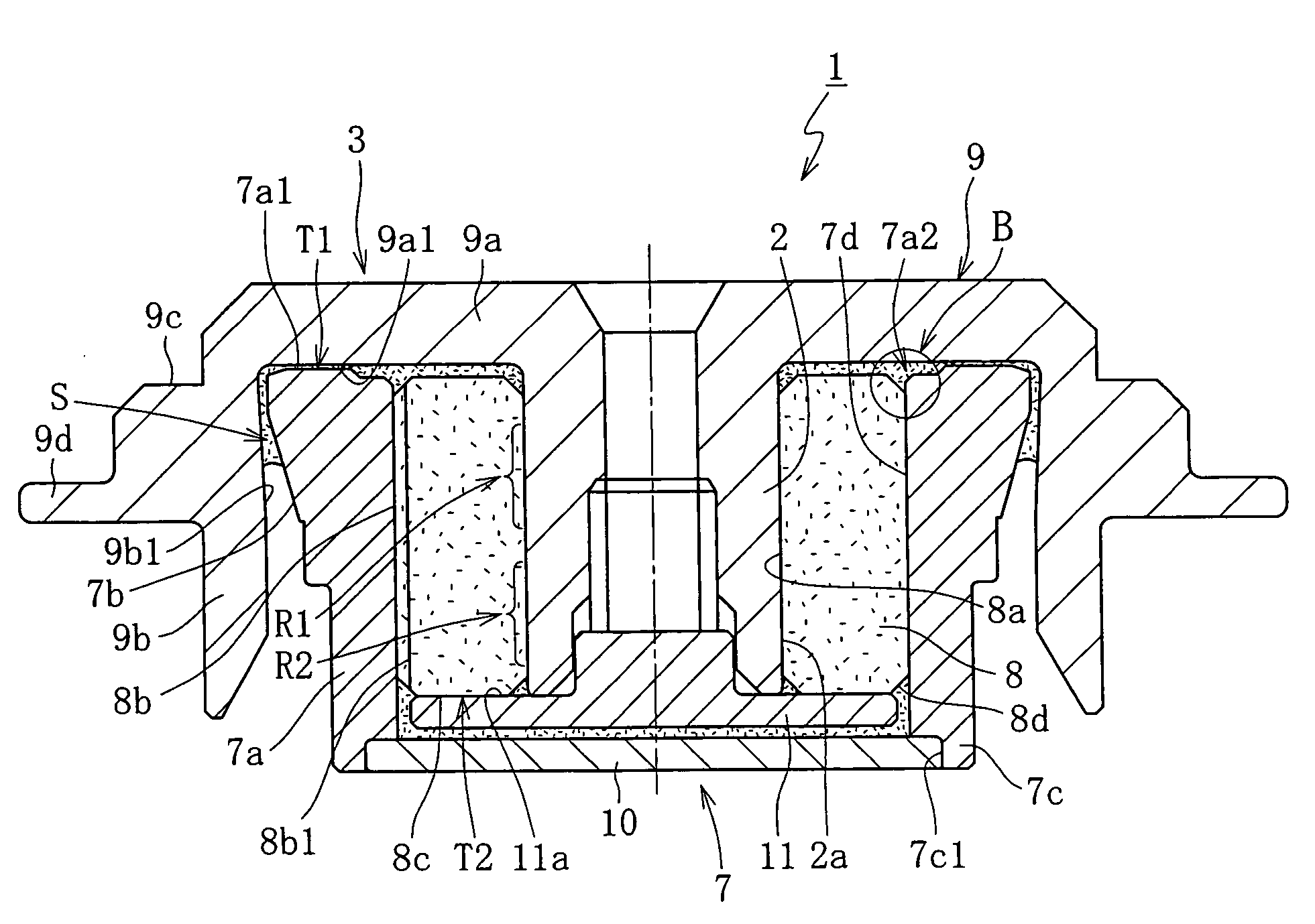
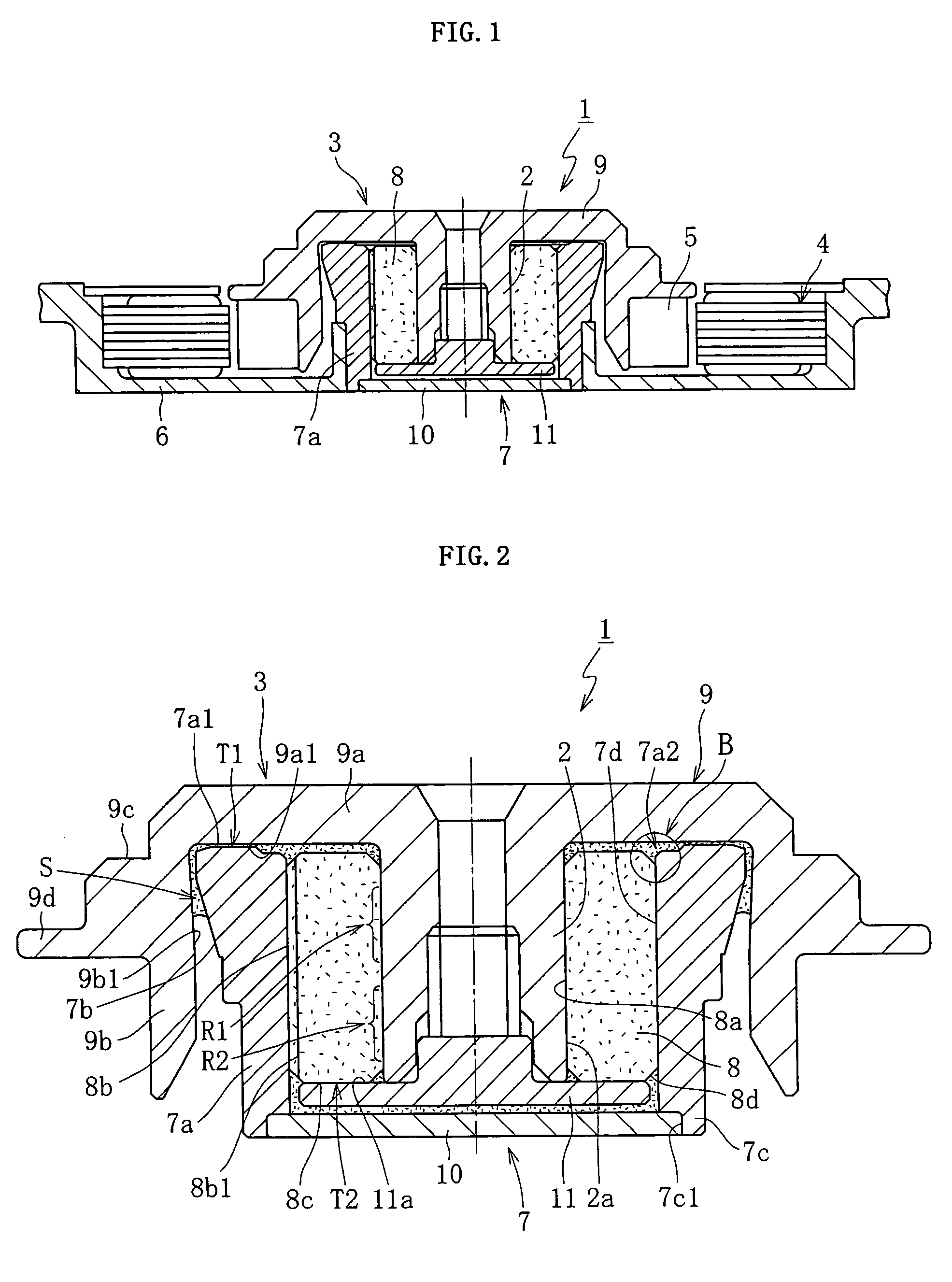
[0033]FIG. 1 shows a construction example of an information apparatus spindle motor in which a fluid dynamic bearing device 1 according to this embodiment is incorporated. This spindle motor is used in a disk drive apparatus, such as an HDD, and is equipped with the fluid dynamic bearing device 1 supporting rotatably in a non-contact support a rotary member 3 equipped with a shaft portion 2, a stator coil 4 and a rotor magnet 5 opposed to each other through the intermediation, for example, of a radial gap, and a motor bracket (retaining member) 6. The stator coil 4 is mounted to the outer periphery of the motor bracket 6, and the rotor magnet 5 is mounted to the outer periphery of the rotary member 3. A housing 7 of the fluid dynamic bearing device 1 is fixed to the inner periphery of the motor bracket 6 by press-fitting / adhesion, etc. One or a plurality of disc-like infor...


PUM

PropertyMeasurementUnit
dynamic pressureaaaaaaaaaa
axial dimensionaaaaaaaaaa
speedaaaaaaaaaa

Abstract

A fluid dynamic bearing device is mainly composed of a housing, a bearing sleeve, and a rotary member. The housing is formed by a side portion formed through injection molding of a resin material, and a bottom member fixed to a fixing portion provided in the inner periphery at one axial end of the side portion and adapted to close an opening at one axial end of the side portion. The fixing portion is a molding surface formed through solidification, in conformity with the inner surface of the mold, of the resin injected by the injection molding.

Description

BACKGROUND OF THE INVENTION[0001]1. Field of the Invention[0002]The present invention relates to a fluid dynamic bearing device rotatably supporting a shaft member by a dynamic pressure action in a non-contact support through the intermediation of a fluid (lubricating fluid) generated in a radial bearing gap. This bearing device is suitable for use in a spindle motor of an information apparatus, for example, a magnetic disc apparatus, such as an HDD or an FDD, an optical disc apparatus, such as a CD-ROM, a CD-R / RW, or a DVD-ROM / RAM, or a magneto-optical disc apparatus, such as an MD or an MO, the polygon scanner motor of a laser beam printer (LBP), or the small motor of an electric apparatus, such as an axial flow fan.[0003]2. Description of the Related Art[0004]Apart from high rotational accuracy, an improvement in speed, a reduction in cost, a reduction in noise, etc. are required of the motors as mentioned above. One of the factors determining such requisite performances is the b...

Claims


Application Information

Patent Timeline
Patent Type & Authority Patents(United States)
IPC IPC(8): F16C32/06B21K1/26F16C17/10
CPCF16C17/107F16C33/103F16C33/107G11B19/2018H02K7/085F16C33/1075Y10T29/49659F16C2370/12F16C17/028
Inventor KURIMURA, TETSUYAINAZUKA, YOSHIHARUTAMAOKA, TAKEHITO
Owner NTN CORP
Why Eureka
Try Eureka