Injection-locked frequency divider

a technology of injection-locked frequency dividers and dividers, which is applied in the direction of oscillator generators, pulse techniques, counting chain pulse counters, etc., can solve the problems of limited locking range and division ratio, inability to support frequency division ratios of even numbers, and inability to introduce considerable noise degradation in high-speed digital dividers

Inactive Publication Date: 2009-07-07
UNIVERSITY OF ROCHESTER
View PDF2 Cites 56 Cited by
  • Summary
  • Abstract
  • Description
  • Claims
  • Application Information

AI Technical Summary

Benefits of technology

[0009]It is another object of the invention to provide an ILFD which can generate signals in cases other than quadrature cases.

Problems solved by technology

Due to large power dissipation, high-speed digital dividers can also introduce considerable noise degradation.
The disadvantages of ILFDs are the limited locking range and division ratio.
On the other hand, it can only support frequency division ratio of even numbers (2, 4, 6 . . . ) due to the differential nature.
Their disadvantages are limited bandwidth per stage, large signal attenuation, and noise degradation.
Ring and coupled oscillators can also be used to generate accurate multi-phase signals, but they suffer from inferior phase noise performance, especially at high frequencies.
However, their phase accuracy depends on the input signal duty-cycle, and the large power consumption is also a concern at high frequencies.
The application of ILFDs in signal generation is so far limited to quadrature cases.

Method used


Image

  • Injection-locked frequency divider
  • Injection-locked frequency divider
  • Injection-locked frequency divider

Examples


Embodiment Construction

[0039]Preferred embodiments of the invention will be set forth in detail with reference to the drawings, in which like reference numerals refer to like elements throughout.

[0040]A first preferred embodiment and variations thereon will now be disclosed.

[0041]To provide frequency division by odd numbers and maintain the differential topology, we construct a differential cascode topology, shown in FIG. 3 as 300, by adding another differential pair of transistors 302 M3 and 304 M4. M3 and M4 convert the differential injection signal Vinj into differential currents, which mix with M1 and M2. M1 and M2 are no longer a differential pair because their source terminals are separated. Now the even-order nonlinearity of M1 (similarly M2) can generate the desired mixing product that corresponds to a division ratio of any odd number, e.g., 3.

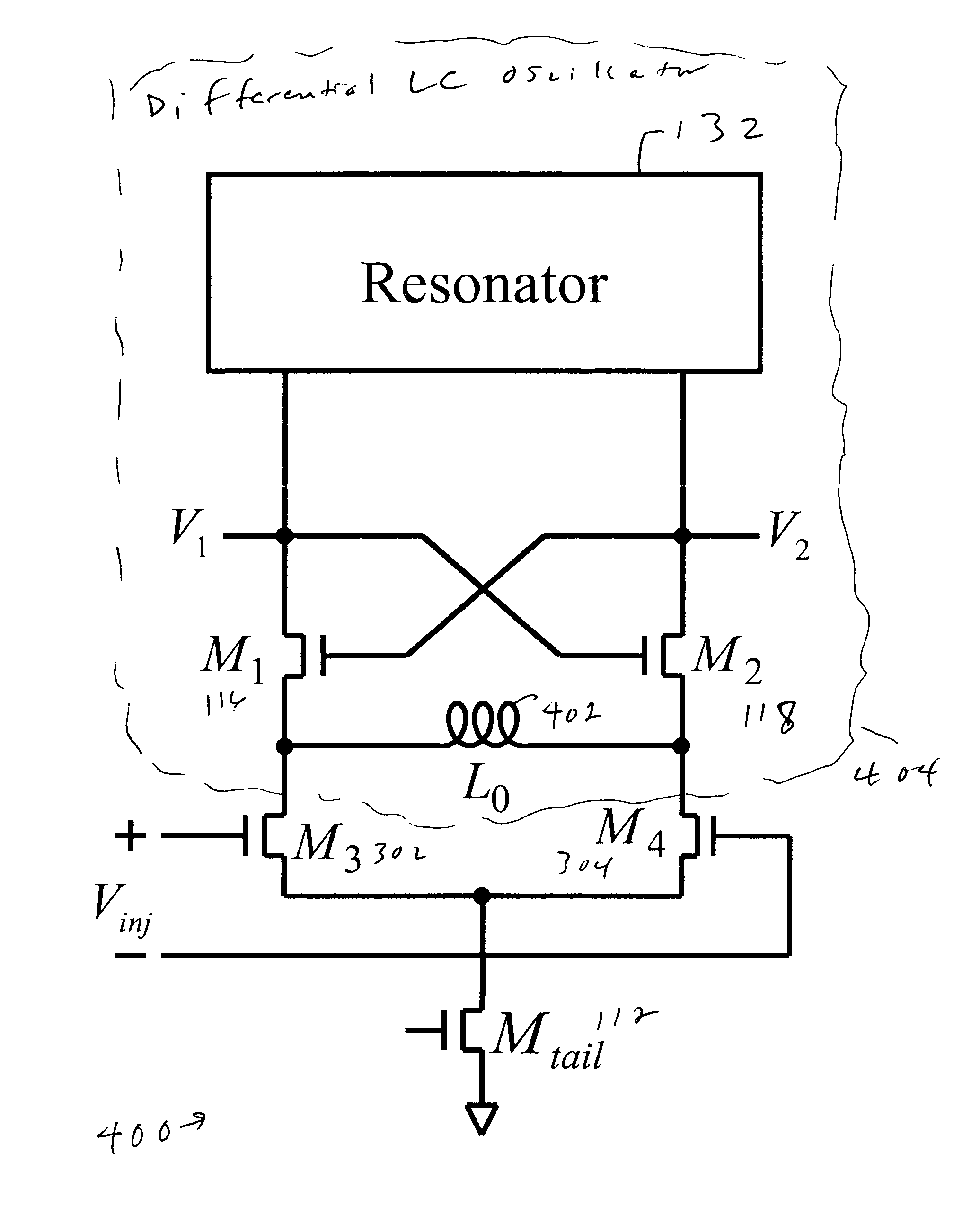
[0042]In an enhanced version of the topology, shown in FIG. 4 as 400, a shunt-peaking inductor 402 having value L0 can be inserted between the source termin...


PUM


Abstract

An injection-locked frequency divider (ILFD) can go beyond simple frequency division by an even number. In one embodiment, another differential pair of transistors is added to convert the injection signal into differential currents, which are mixed in the original transistor pair such as that of the conventional ILFD shown above. In another, a double-balanced ILFD structure includes multiple ILFD's which are independently tunable to allow phase differences other than quadrature.

Description

REFERENCE TO RELATED APPLICATION[0001]The present application claims the benefit of U.S. Provisional Patent Application No. 60 / 731,492, filed Oct. 31, 2005, whose disclosure is hereby incorporated by reference in its entirety into the present disclosure.FIELD OF THE INVENTION[0002]The present invention is directed to an injection-locked frequency divider and more particularly to an injection-locked frequency divider which expands the capabilities of existing injection-locked frequency dividers beyond simple frequency division by an even number.DESCRIPTION OF RELATED ART[0003]Frequency dividers are essential building blocks in wireless and wireline communications as well as radar systems for functions such as frequency synthesis, quadrature signal generation, MUX / DEMUX, and bandwidth compression. Currently, static or dynamic “digital” dividers are commonly used in these RF / microwave systems because it is widely believed that they have simpler structure, larger bandwidth, and better r...

Claims


Application Information

Patent Timeline
Patent Type & Authority Patents(United States)
IPC IPC(8): H03B19/12
CPCH03B19/14
Inventor WU, HUI
Owner UNIVERSITY OF ROCHESTER
Why Eureka
Try Eureka