Method for refrigerant pressure control in refrigeration systems

a technology of refrigerant pressure control and refrigeration system, which is applied in the direction of refrigeration machines, lighting and heating apparatus, refrigeration safety arrangements, etc., can solve the problems of lowering the temperature of refrigerant at the evaporator, and reducing the available heat transfer surface, so as to increase the system pressure

Active Publication Date: 2009-07-14
JOHNSON CONTROLS TYCO IP HLDG LLP
View PDF151 Cites 45 Cited by
  • Summary
  • Abstract
  • Description
  • Claims
  • Application Information

AI Technical Summary

Benefits of technology

[0014]Another advantage of the present invention is that the air conditioning or heat pump unit can operate at lower ambient temperatures. The method and system of the present invention provides an increase in system pressure, thereby allowing the system to operate at lower ambient temperatures without icing of the system components.

Problems solved by technology

The decrease in head pressure results in a lowering of the temperature of the refrigerant at the evaporator.
When the temperature of the refrigerant at the evaporator becomes too low, icing of the system can occur.
The ice formed by the water frozen on the surface reduces the available heat transfer surface and eventually prevents the proper operation of the HVAC system by inhibiting heat transfer and / or damaging system components.
The use of the variable speed condenser fan or a plurality of condenser fans having independent controls has the drawback that it is expensive and requires complicated wiring and controls.
The reduced surface area thereby reduces the ability of the condenser to remove heat from the refrigerant.
The use of parallel refrigerant condensers has the drawback that it requires an additional condenser coil and additional piping, thereby increasing the space and cost required for installation.
Another drawback associated with refrigerant flooding of the condenser coil is the resultant decrease in system capacity.
Refrigerant normally available in a properly operating system is trapped in the condenser coil and not available to the compressor, thereby decreasing system capacity.
Alternatively, the valve is closed to stop the flow until the level of refrigerant rises in the condenser in an amount that reduces the effective cooling surface of the condenser.
The reduced surface area thereby reduces the ability of the condenser to remove heat from the refrigerant, thereby raising the pressure of the system.
The use of a pressure-response valve and a vessel downstream of the condenser to maintain control of the amount of condensing surface has the drawback that it includes a specially designed valve and additional piping, thereby increasing the required space and cost.
As discussed above, another one of the drawbacks with refrigerant flooding the condenser coil is decreased system capacity.
Refrigerant normally available in a properly operating system is trapped in the condenser coil and not available to the compressor, thereby decreasing system capacity.
The use of a bypass has the drawback that it includes a specially designed valve and additional piping, thereby increasing the required space and cost.

Method used


Image

  • Method for refrigerant pressure control in refrigeration systems
  • Method for refrigerant pressure control in refrigeration systems
  • Method for refrigerant pressure control in refrigeration systems

Examples


Embodiment Construction

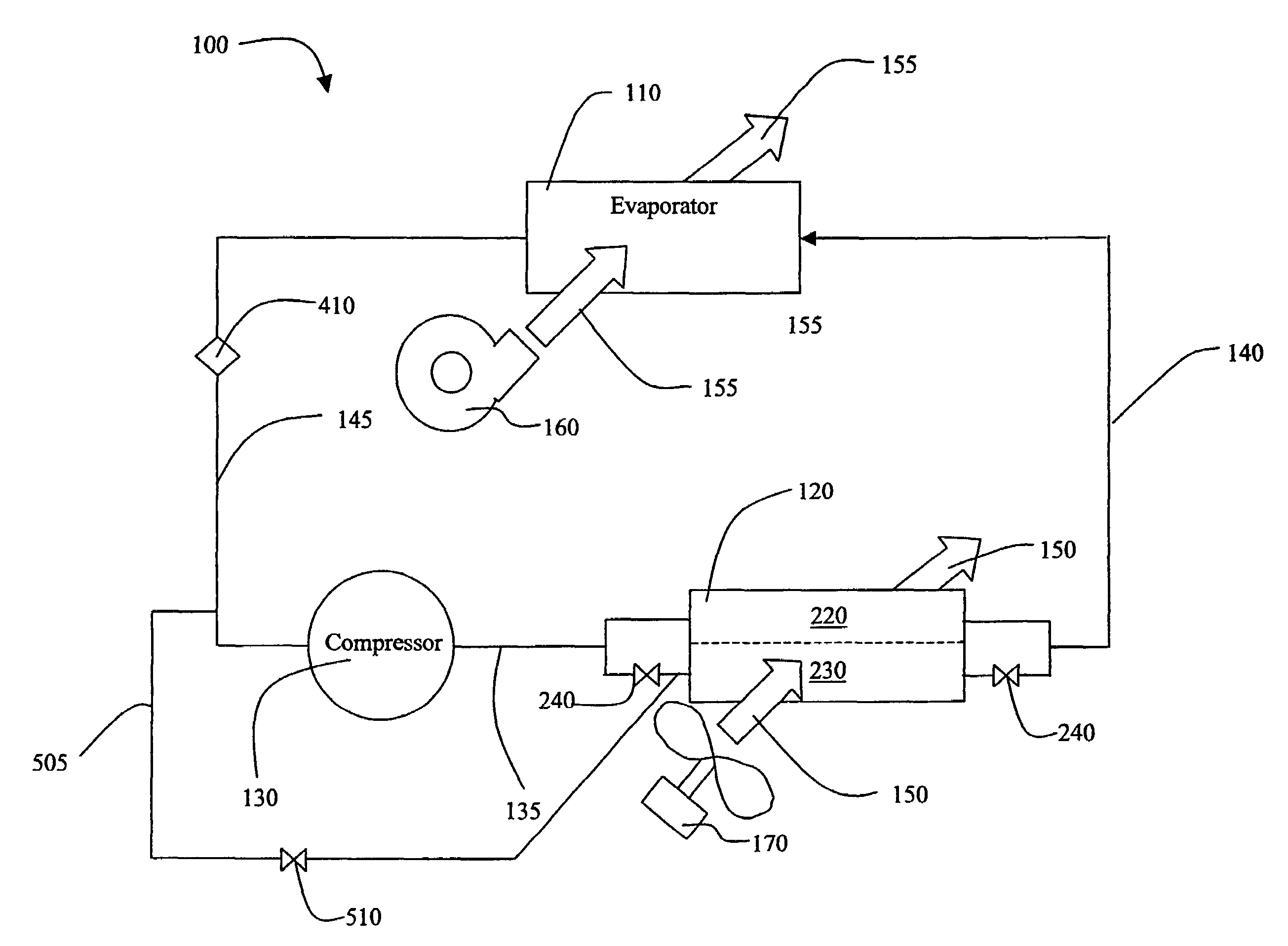
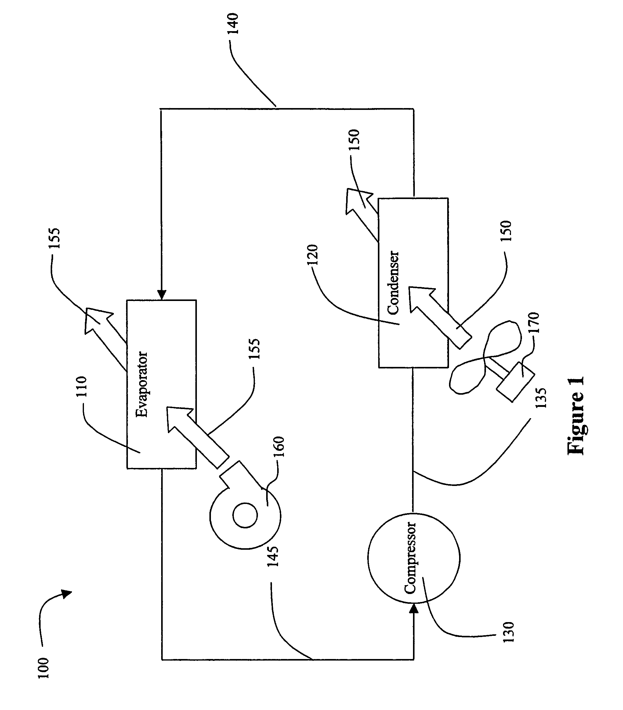
[0024]FIG. 1 illustrates an HVAC, refrigeration, or chiller system 100. Refrigeration system 100 includes a compressor 130, a condenser 120, and an evaporator 110. The compressor 130 compresses a refrigerant vapor and delivers it to the condenser 120 through compressor discharge line 135. The compressor 130 is preferably a reciprocating or scroll compressor, however, any other suitable type of compressor can be used, for example, screw compressor, rotary compressor, and centrifugal compressor. The refrigerant vapor delivered by the compressor 130 to the condenser 120 enters into a heat exchange relationship with a first heat transfer fluid 150 and undergoes a phase change to a refrigerant liquid as a result of the heat exchange relationship with the fluid 150. Suitable fluids for use as the first heat transfer fluid 150 include, but are not limited to, air and water. The first heat transfer fluid 150 is moved by use of a fan 170, which moves the first heat transfer fluid 150 through...


PUM


Abstract

A method and system for controlling refrigerant pressure in an HVAC system. The method includes providing a compressor, a condenser and an evaporator connected in a closed refrigerant loop. The condenser has a header arrangement capable of distributing refrigerant to a plurality of refrigerant circuits within the condenser. The header arrangement also is capable of selectively isolating at least one of the circuits from refrigerant flow. Refrigerant pressure is sensed at a predetermined location in the refrigeration system. At least one of the circuits is isolated when the refrigerant pressure is less than or equal to a predetermined pressure.

Description

FIELD OF THE INVENTION[0001]The present invention relates generally to heating, ventilation and air conditioner HVAC systems. In particular, the present invention is related to methods and / or systems that control HVAC system refrigerant pressure.BACKGROUND OF THE INVENTION[0002]An HVAC system generally includes a closed loop refrigeration system with at least one evaporator, at least one condenser and at least one compressor. As the refrigerant travels through the evaporator, it absorbs heat from a heat transfer fluid to be cooled and changes from a liquid to a vapor phase. After exiting the evaporator, the refrigerant proceeds to a compressor, then a condenser, then an expansion valve, and back to the evaporator, repeating the refrigeration cycle. The fluid to be cooled (e.g. air) passes through the evaporator in a separate fluid channel and is cooled by the evaporation of the refrigerant. The cooled fluid can then be sent to a distribution system for cooling the spaces to be condi...

Claims


Application Information

Patent Timeline
Patent Type & Authority Patents(United States)
IPC IPC(8): F25B41/00
CPCF25B49/027F25B2700/19F25B2600/2519F25B2600/2517
Inventor KNIGHT, JOHN TERRYLANDERS, ANTHONY WILLIAMGAVULA, PATRICK GORDONPICKLE, STEPHEN BLAKE
Owner JOHNSON CONTROLS TYCO IP HLDG LLP
Why Eureka
Try Eureka