
MEMS fiber optic microphone

a fiber optic microphone and diaphragm technology, applied in the direction of instruments, measurement devices, using wave/particle radiation means, etc., can solve the problems of ineffectiveness, non-functional fiber optic microphones, etc., and achieve the effect of reducing the interference gap width

Active Publication Date: 2009-07-14
PUBLIC SERVICE ELECTRIC & GAS +1
View PDF15 Cites 9 Cited by
  • Summary
  • Abstract
  • Description
  • Claims
  • Application Information

AI Technical Summary

Benefits of technology

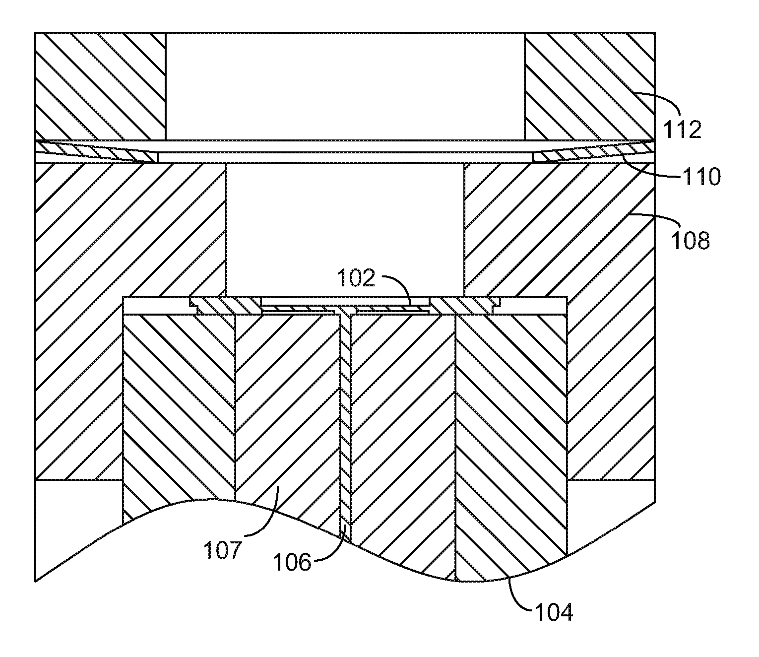
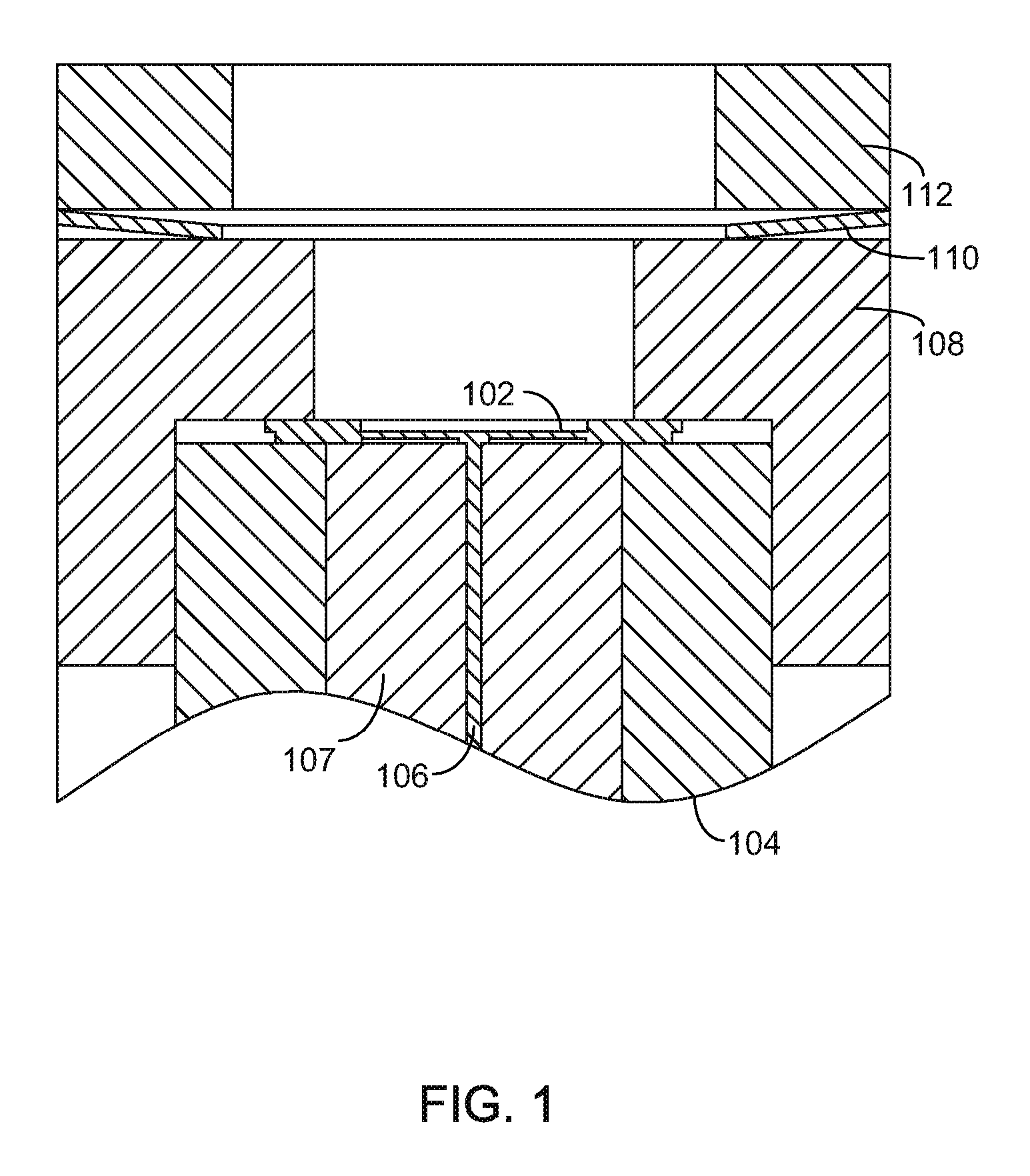
[0004]The present invention is a Fabry-Perot diaphragm fiber optic microphone, which was fabricated with MEMS (micro electric mechanical system) technology. In one embodiment, the microphone contains a diaphragm which is clamped to the ferrule of the single mode fiber. The diaphragm structure may contain three thicknesses which control various frequency responses. The inner area can be embossed to minimize the interference gap width between the diaphragm and the fiber endface as well as ensure proper alignment between the fiber and the diaphragm.

Problems solved by technology

Fiber optic microphones have been proposed [1-3] however, they are non-functional or ineffective because they are either interference based, utilizing a piece or coil of optical fiber as the sensing element, or intensity based, using a diaphragm as the pressure wave sensing element.

Method used


Image

  • MEMS fiber optic microphone
  • MEMS fiber optic microphone
  • MEMS fiber optic microphone

Examples


Embodiment Construction

Definition Of Symbols

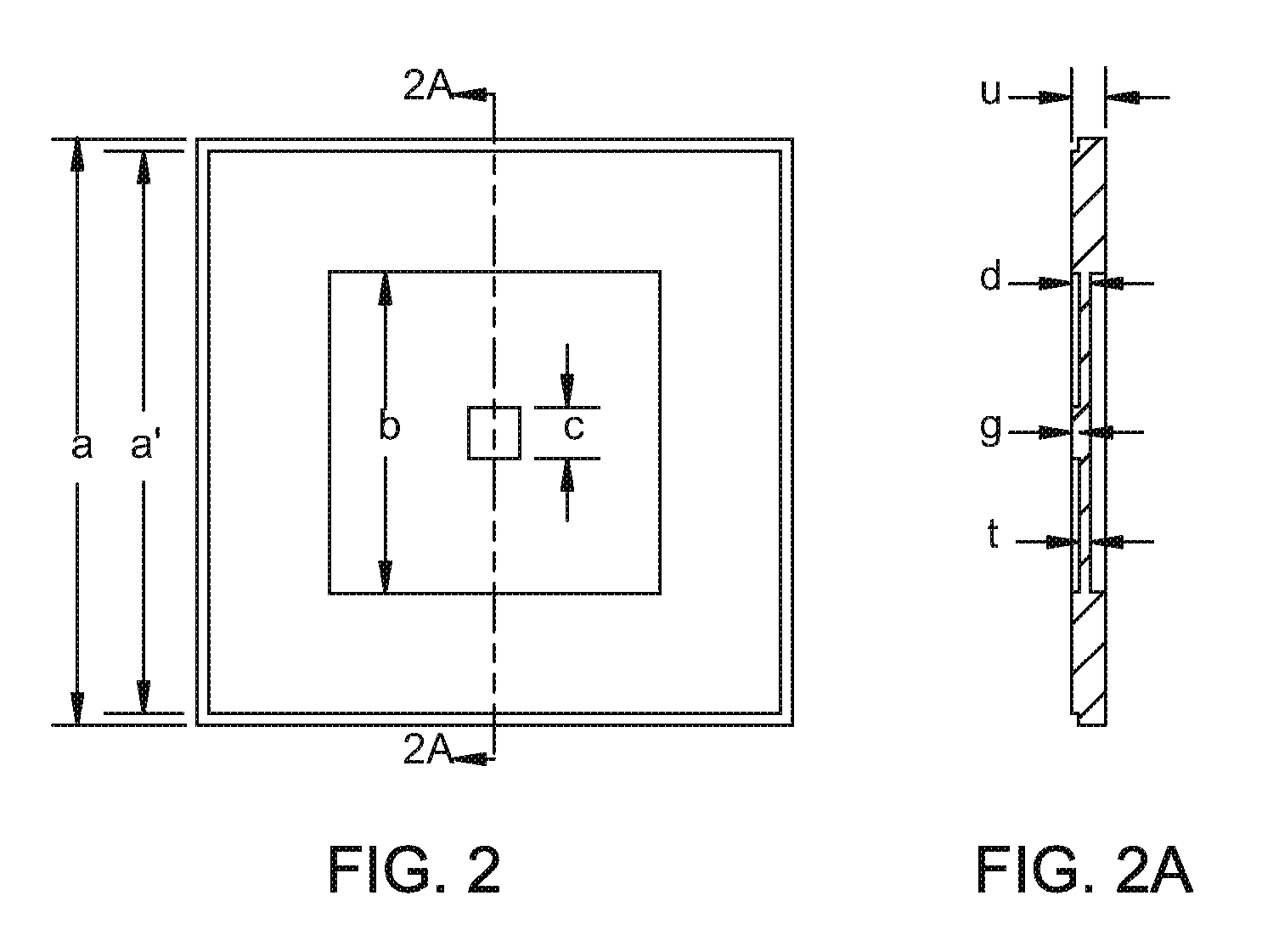
[0011]VFP the output voltage of the DFOS[0012]VFPo the maximum of output voltage of the DFOS[0013]n refractive index of the medium; for air n˜1[0014]λ wavelength of the light used for the DFOS[0015]L the width of the narrow gap between the back of the diaphragm and the end surface of the single mode optic fiber[0016]Lo the equilibrium width of the narrow gap diaphragm and the optic fiber[0017]φo the Q-point phase factor determined by the equilibrium width of the interference gap[0018]E Young's modulus of the material of the diaphragm[0019]ν Poisson coefficient of the material of the diaphragm[0020]η the constant of proportionality in the equation of displacement versus pressure, which is dependent on the geometric shape of the diaphragm[0021]u the thickness of the silicon wafer (or other material) used for the fabrication of the DFOS diaphragm[0022]t the thickness of the diaphragm of the DFOS[0023]a the square silicon chip (or other material) size of the DFOS[00...


PUM


Abstract

The theory, design, fabrication, and characterization of MEMS (micro electrical mechanical system) Fabry-Perot diaphragm-fiber optic microphone are described in the present invention. By using MEMS technology in processing and packaging, a square 1.9 mm×1.9 mm, 2 μ thick SiO2 diaphragm with a 350 μ square embossed center of silicon is mechanically clamped to the ferrule of a single mode fiber to keep its closeness (5 μ) and perpendicular orientation with respect to the diaphragm. Static measurement of optical output power versus the pressure on membrane reveals more than one period of Fabry-Perot interference, thereby generating a Fabry-Perot diaphragm-fiber interferometer device accurately reproducing audible acoustic wave.

Description

CROSS REFERENCE TO RELATED APPLICATIONS[0001]This application claims the benefit of U.S. Provisional Application No. 60 / 801,910 entitled “MEMS Fiber Optic Microphone” filed May 19, 2006 which is incorporated by reference herein in its entirety and U.S. Provisional Application No. 60 / 801,943 entitled “Aligned Embossed Diaphragm Based Fiber Optic Sensor” filed May 19, 2006 which is incorporated herein by reference in its entirety.FIELD OF THE INVENTION[0002]This invention involves the design and fabrication of a new Fabry-Perot diaphragm-fiber optic microphone by using MEMS technology in processing and packaging. The currently described microphone permits direct amplification of audible signal without requiring modulation or demodulation.BACKGROUND OF THE INVENTION[0003]Commercially available microphones or acoustic sensors in the audible frequency range (20-20,000 Hz) convert mechanical pressure wave to electrical signal (current or voltage). Fiber optic microphones have been propose...

Claims


Application Information

Patent Timeline
Patent Type & Authority Patents(United States)
IPC IPC(8): G01B9/02
CPCG01L9/0079G01H9/004
Inventor CHIN, KEN K.FENG, GUANHUAROMAN, HARRY
Owner PUBLIC SERVICE ELECTRIC & GAS
Learn More