
High-pressure processing apparatus and high-pressure processing method

Inactive Publication Date: 2009-07-21
DAINIPPON SCREEN MTG CO LTD +1
View PDF7 Cites 4 Cited by
  • Summary
  • Abstract
  • Description
  • Claims
  • Application Information

AI Technical Summary

Benefits of technology

[0008]A primary object of the invention is to achieve the construction simplification and cost reduction of the high-pressure processing apparatus and method for subjecting a surface of a process subject to a predetermined surface treatment by allowing a process fluid to contact the surface of the process subject, the process fluid prepared by mixing a high-pressure fluid with all or any one(s) of plural chemical agents.
[0011]With such a structure according to the present invention, the process fluid is prepared by mixing the high-pressure fluid with all or any one(s) of plural chemical agents as required, and then the surface treatment for the process subject is carried out with the process fluid. The mixing the high-pressure fluid with the chemical agent(s) is carried out as follows. First, the chemical formulation is prepared by blending together all or selected one(s) of plural chemical agents before the mixing. Next, the chemical formulation is pumped into the high-pressure fluid or the processing chamber, the above mixing is carried out. In this manner, the present invention has an arrangement to pump the chemical formulation into the high-pressure fluid pumped to the processing chamber or pump the chemical formulation to the processing chamber after the chemical formulation is prepared under low-pressure, instead of pumping the plural chemical agents to be mixed with the high-pressure fluid individually like the conventional apparatus. Therefore, the number of components for pumping the chemical agents (such as the high-pressure pump, high-pressure valve and high-pressure pipe) can be reduced and a pipe line for pumping the chemical agents can be simplified to achieve a notable cost reduction of the apparatus.
[0014]With such a structure according to the present invention, similarly to the above high-pressure processing apparatus, the chemical formulation is prepared by blending together all or selected one(s) of plural chemical agents, and then the process fluid is formed by pumping the chemical formulation into the high-pressure fluid or the processing chamber to be mixed with the high-pressure fluid. Therefore, a surface treatment on the process subject can be carried out in a simple construction of the apparatus , and at low cost.
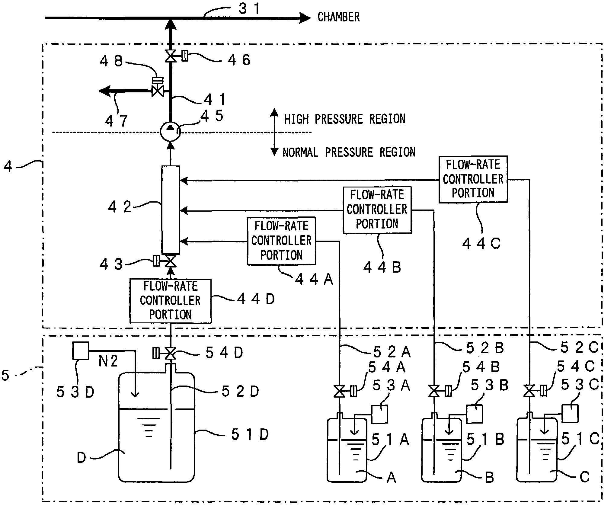
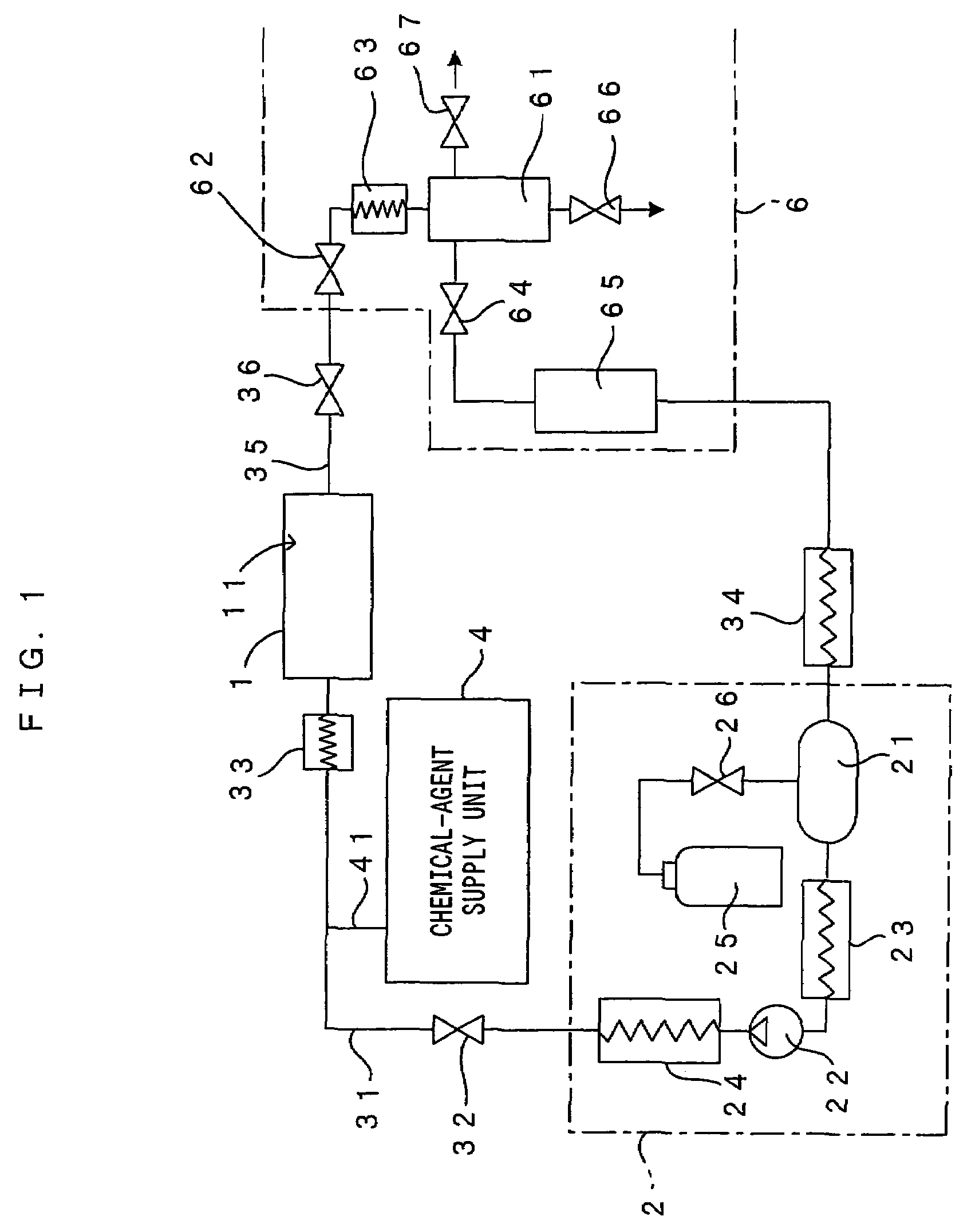
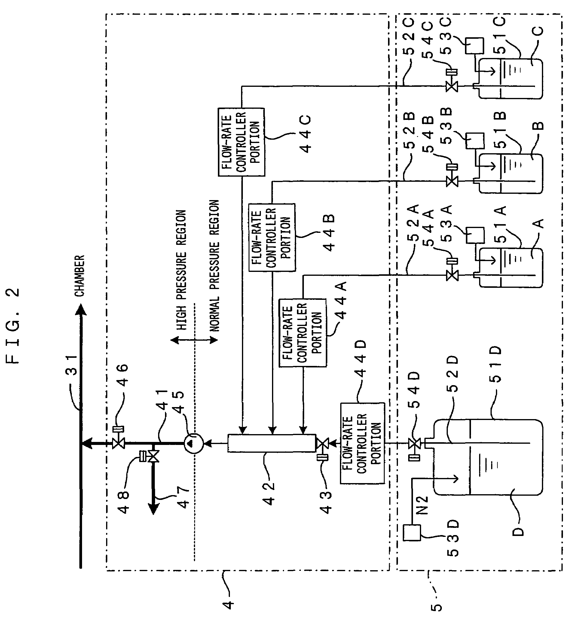
[0020]Where the detergent component such as the aforementioned basic compound is poorly soluble in the high-pressure fluid, it is preferred to employ, as the chemical agent, a compatibilizer capable of serving as an auxiliary for dissolving or homogeneously dispersing the detergent component in the high-pressure fluid. The compatibilizer also acts to prevent re-adherence of contaminants in the rinsing step following the cleaning step. Furthermore, the compatibilizer also effectively promotes the removal of the auxiliary (chemical agent) from high-pressure pipes 41, 31 extended from a mixing valve assembly 42 (FIG. 2) to a pressure vessel 1 (FIG. 1) and a high-pressure pump 45; a high-pressure valve 46; a heater 33; and the pressure vessel 1 interposed in the high-pressure pipe, the auxiliary used in the cleaning step.

Problems solved by technology

The pressure pump is generally expensive and hence, the increase in the number of pressure pumps provided directly results in an increased cost of the high-pressure processing apparatus.
This tendency constitutes one of major factors increasing the fabrication costs of the high-pressure processing apparatus.
This entails a similar problem to the above.
This results in the increased fabrication costs of the high-pressure processing apparatus.
Furthermore, the pipe line is complicated, leading to another problem that the construction of the apparatus is complicated.

Method used


Image

  • High-pressure processing apparatus and high-pressure processing method
  • High-pressure processing apparatus and high-pressure processing method
  • High-pressure processing apparatus and high-pressure processing method

Examples


Embodiment Construction

[0030]FIG. 1 is a diagram showing a high-pressure processing apparatus according to one embodiment of the invention. The high-pressure processing apparatus is adapted to introduce, as a process fluid, supercritical carbon dioxide or a mixture of supercritical carbon dioxide and a chemical agent into a processing chamber 11 formed internally of a pressure vessel 1, and to perform predetermined cleaning process, rinsing process and drying process on a substrate such as a substantially circular semiconductor wafer (process subject) retained in the processing chamber 11. The arrangement and operations of the apparatus will hereinbelow be described in details.

[0031]The high-pressure processing apparatus is provided with a high-pressure fluid supply unit 2 for pumping supercritical carbon dioxide (hereinafter referred to as “SCF”), as the “high-pressure fluid” of the invention, to the processing chamber 11. The high-pressure fluid supply unit 2 includes a reservoir 21 for high-pressure fl...


PUM

PropertyMeasurementUnit
Pressureaaaaaaaaaa
Flow rateaaaaaaaaaa

Abstract

A mixing valve assembly 42 is communicated with a dedicated tank 51D, storing therein a compatibilizer D, via an inlet valve 43 and is also communicated with dedicated tanks 51A-51C via three injection valves, the tanks storing therein auxiliaries A-C respectively. A chemical formulation is prepared by selectively injecting any one(s) of four chemical agents into the mixing valve assembly 42 by way of on-off control of the inlet valve 43 and the injection valves and blending together the injected chemical agents. Then, the chemical formulation is pumped into SCF by a high-pressure pump 45 such that the SCF and the chemical formulation are mixed together to form a process fluid. Thus, the number of components of a high-pressure portion can be reduced to achieve a cost reduction of an apparatus. Furthermore, a pipe line for pumping the chemical agents is simplified.

Description

BACKGROUND OF THE INVENTION[0001]1. Field of the Invention[0002]The present invention relates to a high-pressure processing apparatus and a high-pressure processing method which subject a surface of a process subject to a predetermined surface treatment by allowing a process fluid to contact the surface of the process subject, the process fluid comprising a high-pressure fluid or a mixture of the high-pressure fluid and a chemical agent. The process subject includes a variety of substrates such as semiconductor wafers, glass substrates for photomask, glass substrates for liquid crystal display, glass substrates for plasma display, and optical disk substrates (hereinafter, simply referred to as “substrate”).[0003]2. Description of the Related Art[0004]In a case where a resist is used for forming a pattern in a semiconductor fabrication process, a cleaning step is required for removing unwanted substances and contaminants from the substrate, the unwanted substances and contaminants in...

Claims


Application Information

Patent Timeline
IPC IPC(8): B08B3/00B08B3/04G03F7/42B08B3/08B08B7/00H01L21/027H01L21/304
CPCB08B7/0021
Inventor MURAOKA, YUSUKEIWATA, TOMOMISAITO, KIMITSUGUYAMAGATA, MASAHIROOSHIBA, HISANORISARUMARU, SHOGO
Owner DAINIPPON SCREEN MTG CO LTD
Learn More