Piezoelectric element, liquid-jet head and liquid-jet apparatus

a liquid-jet head and piezoelectric element technology, applied in the direction of device material selection, generator/motor, printing, etc., can solve the problems of not being able to obtain a sufficient displacement of piezoelectric elements, similar to other piezoelectric elements, and achieve the effect of significantly improving the effect of ejecting droplets

Active Publication Date: 2009-07-21
SEIKO EPSON CORP
View PDF9 Cites 11 Cited by
  • Summary
  • Abstract
  • Description
  • Claims
  • Application Information

AI Technical Summary

Benefits of technology

[0006]With the aforementioned conditions taken into consideration, an object of the present invention is to provide a piezoelectric element, which can obtain a large distortion with a low drive voltage, a liquid-jet head and a liquid-jet apparatus.
[0012]In the third aspect, since the piezoelectric film has the rhombohedral crystal system structure, it is possible to obtain a large distortion with a low voltage.
[0016]In the fifth aspect, a piezoelectric element which includes a piezoelectric film made of lead zirconate titanate (PZT) and has a priority orientation of the (100) plane with perovskite crystals is used. The piezoelectric film has the diffraction peak position of X-ray derived from the (100) planes of the piezoelectric film is within a range of 2θ=21.79 to 21.88. For this reason, it is possible to provide the liquid-jet head which can obtain a large distortion with a low drive voltage.
[0018]According to the sixth aspect, it is possible to provide a liquid-jet apparatus in which a characteristic of ejecting droplets is significantly improved.

Problems solved by technology

However, it has not been possible to obtain a sufficient displacement with such piezoelectric elements.
The problems are similarly present in other piezoelectric elements.

Method used


Image

  • Piezoelectric element, liquid-jet head and liquid-jet apparatus
  • Piezoelectric element, liquid-jet head and liquid-jet apparatus
  • Piezoelectric element, liquid-jet head and liquid-jet apparatus

Examples


first embodiment

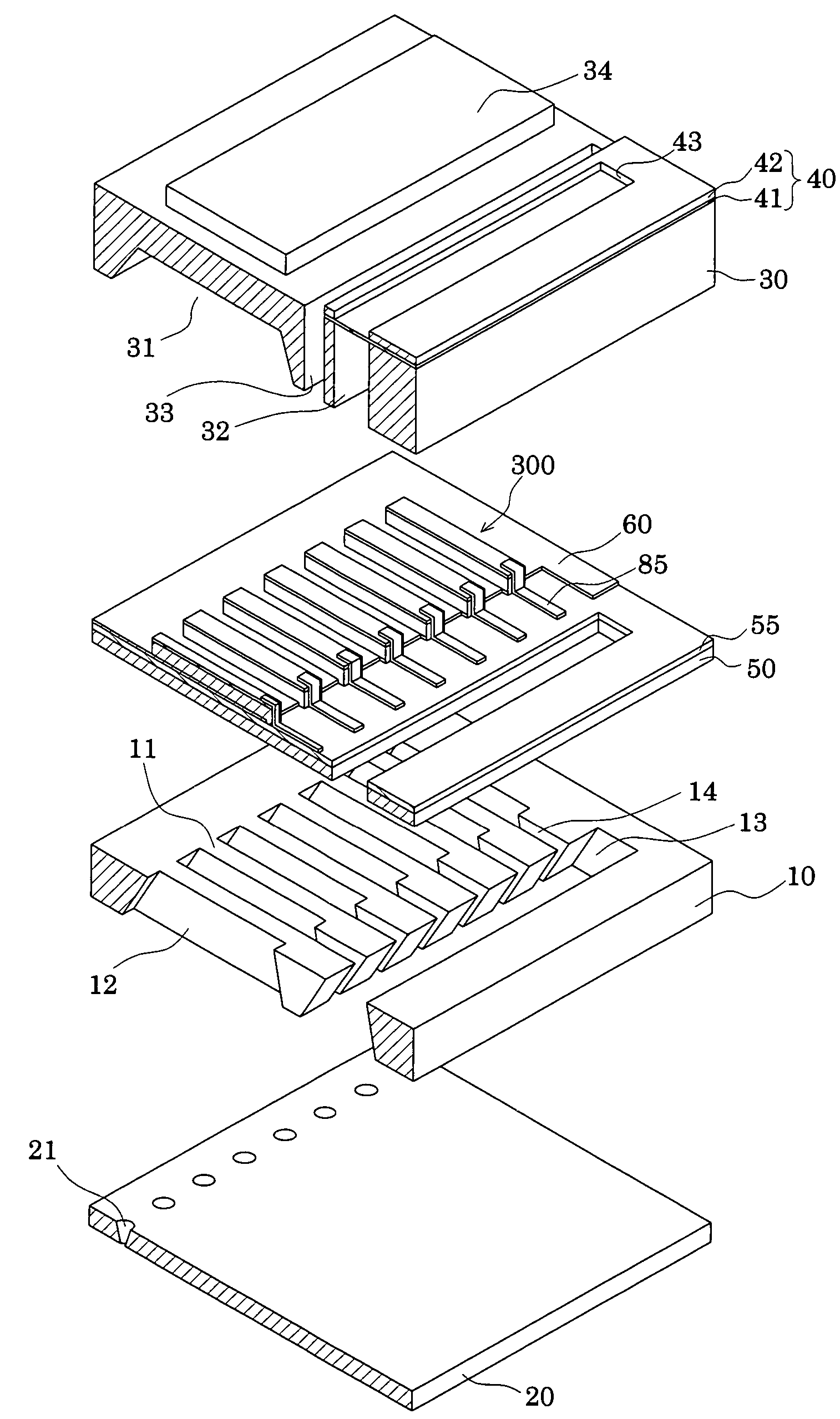
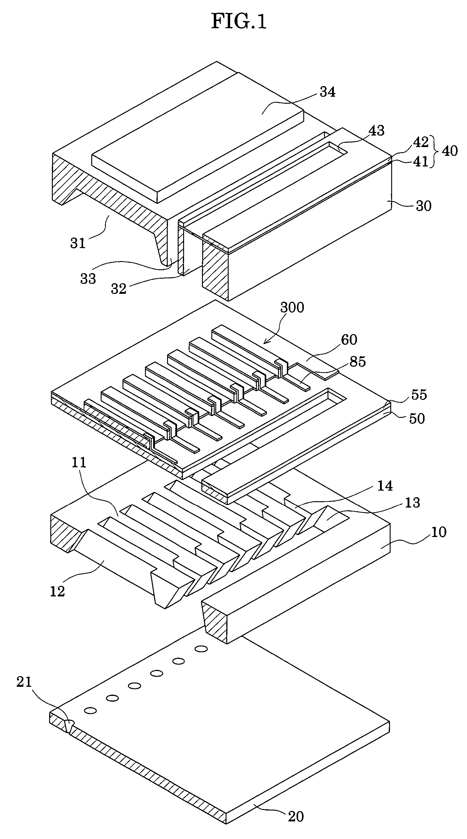
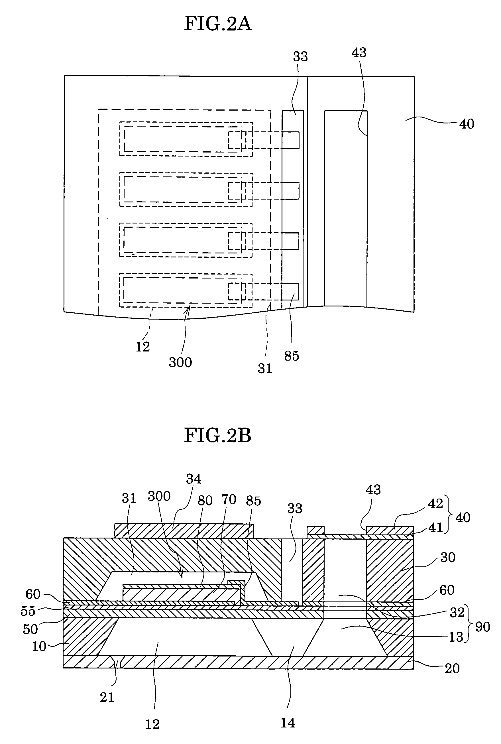
[0025]FIG. 1 is an exploded perspective view of a liquid-jet head according to a first embodiment of the present invention. FIG. 2A is a plan view of the liquid-jet head shown in FIG. 1, and FIG. 2B is a cross-sectional view of the liquid-jet head of FIG. 1.

[0026]As shown in the drawings, a passage-forming substrate 10 is formed of a single crystal silicon substrate where silicon crystals on the face surface of the substrate are in the (110) plane direction, in this embodiment. An elastic film 50 is formed on one of the two surfaces of the passage-forming substrate 10. The elastic film 50 has a thickness of 0.5 to 2 μm and is made of silicon dioxide. Note that, in this embodiment, the elastic film 50 is an amorphous silicon film made of silicon oxide formed by means of thermally oxidizing the passage-forming substrate 10. The elastic film 50 has a flat surface while maintaining the surface state of the passage-forming substrate 10 as it was.

[0027]In the passage-forming substrate 10,...


PUM


Abstract

Disclosed are a piezoelectric element which can obtain a large strain with a low drive voltage, a liquid-jet head and a liquid-jet apparatus. The piezoelectric element includes: a lower electrode; an upper electrode; and a piezoelectric film which is made of lead zirconate titanate (PZT), and which has perovskite crystals having priority orientations of the (100) plane, the piezoelectric film being interposed between the lower electrode and the upper electrode. In the piezoelectric element, an X-ray diffraction peak position derived from the (100) planes of the piezoelectric film is within a range of 2θ=21.79 to 21.88.

Description

[0001]The entire disclosure of Japanese Patent Application No. 2005-097325 filed Mar. 30, 2005 is expressly incorporated by reference herein.FIELD OF THE INVENTION[0002]The present invention relates to a piezoelectric element including a lower electrode, a piezoelectric film and an upper electrode. Additionally, the present invention relates to a liquid-jet head which includes the piezoelectric element and ejects droplets from nozzle orifices, and to a liquid-jet apparatus.DESCRIPTION OF THE PRIOR ART[0003]A piezoelectric element used for a liquid-jet head and the like is an element in which a piezoelectric film is interposed between two electrodes, the piezoelectric film being made of a piezoelectric material showing an electric mechanical conversion function. The piezoelectric film is composed of, for example, crystallized piezoelectric ceramics.[0004]There has been an inkjet recording head with the following configuration. In accordance with the configuration, a part of pressure ...

Claims


Application Information

Patent Timeline
Patent Type & Authority Patents(United States)
IPC IPC(8): B41J2/045H01L41/00B41J2/055B41J2/135B41J2/14B41J2/145H01L41/09H01L41/18H01L41/187H01L41/29H01L41/318H01L41/319H01L41/39
CPCB41J2/14233B41J2/161B41J2/1623B41J2/1629B41J2/1632H01L41/1876H01L41/318B41J2/1646H01L41/0973B41J2002/14241B41J2002/14419H10N30/2047H10N30/8554H10N30/078H10N30/80
Inventor SUMI, KOJIKAZAMA, HIRONOBU
Owner SEIKO EPSON CORP
Why Eureka
Try Eureka