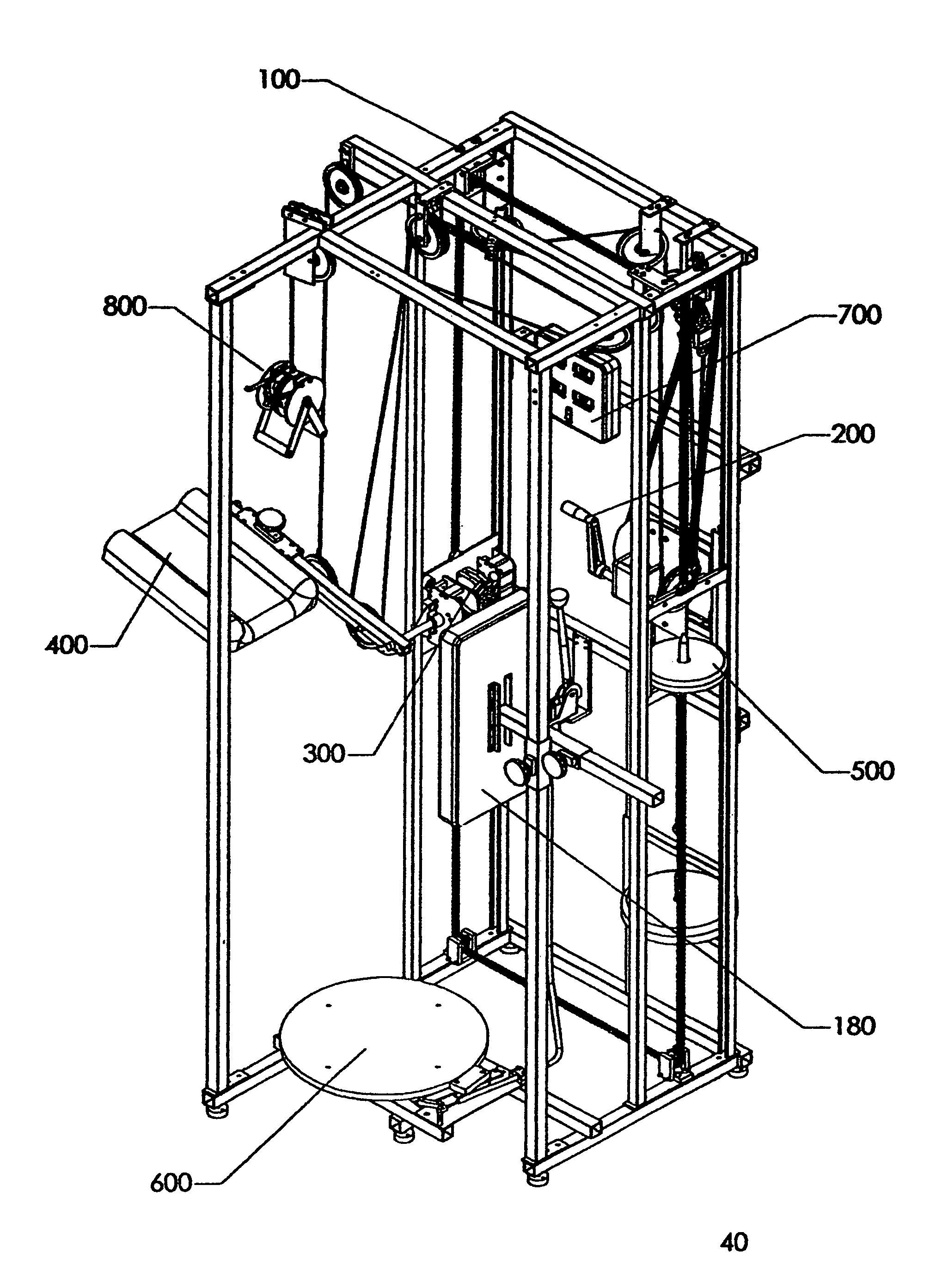
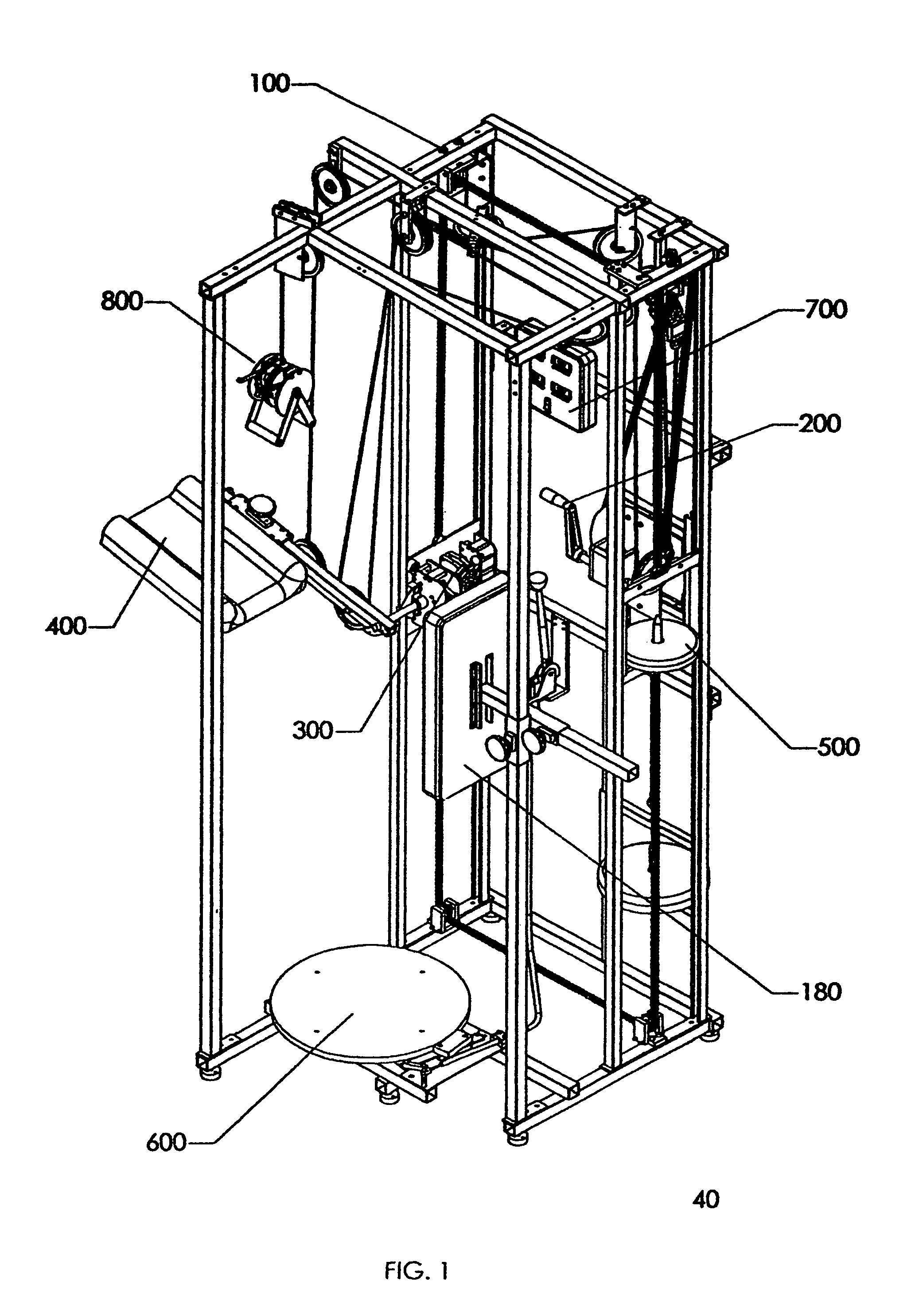
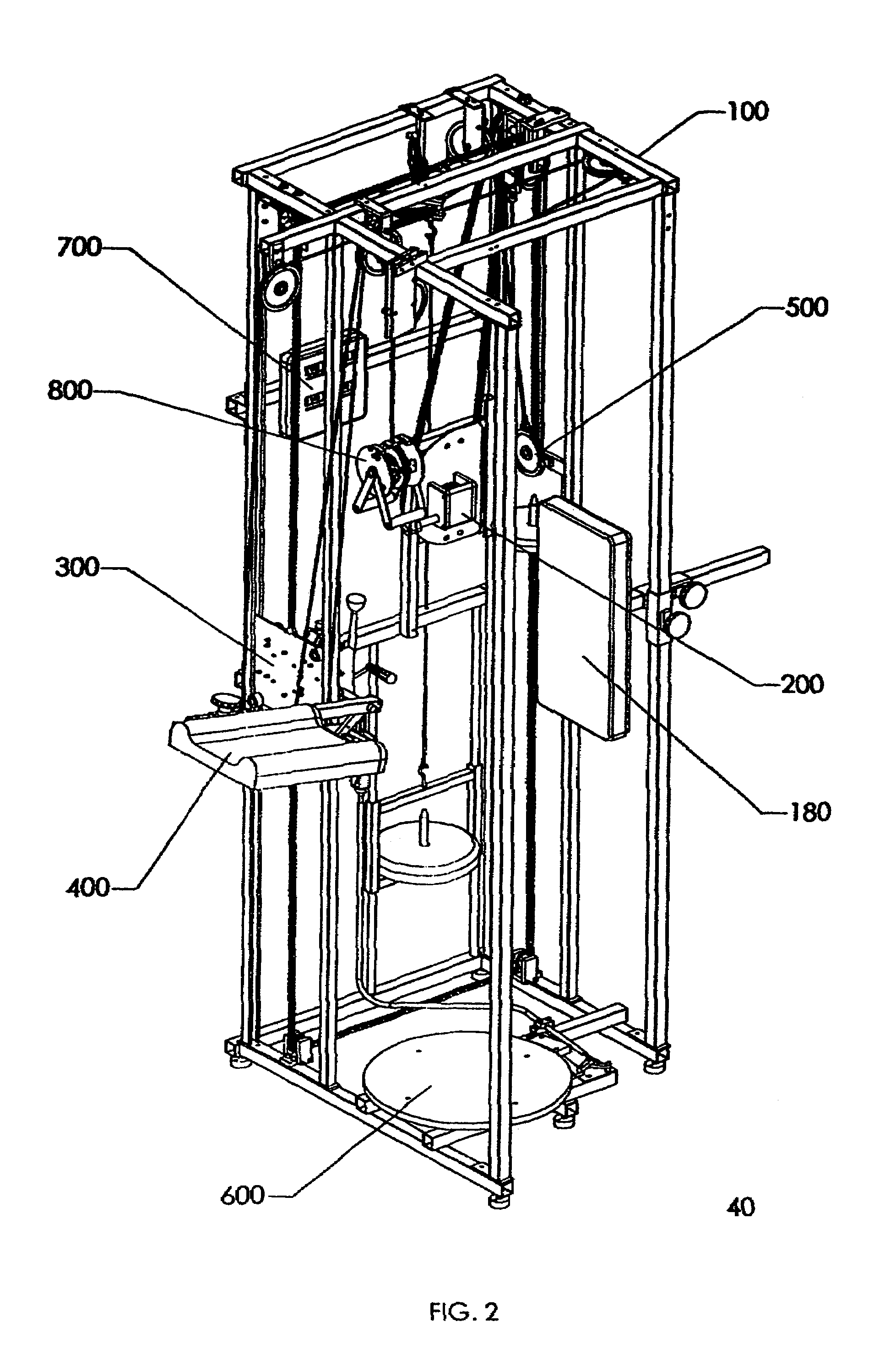
[0012]The counter balance weight stack is fabricated from rigid square in cross section tubes. The weight stack guide is fabricated from rigid circular in cross section tubes. The counter balance weight stack is made in the shape of a rectangle, which allows its short sides to travels up and down along the vertical circular tubes, and allows its lower longer side to accept weights onto its weight pin. Weights are added to the weight stack and this weight provides the counter balance force, which assists the user to lift the leg lift pad subassembly.
[0015]HAND
CRANK SUBASSEMBLY—The hand
crank subassembly is used to change the height of the leg lift subassembly. The hand
crank subassembly is attached to the back right vertical structural member of the frame subassembly through the use of four
crank beams. The hand crank subassembly consists of a hand crank, a worm gear, a worm a
metal housing, a large
sprocket and fastening hardware. The large
sprocket is connected to a much smaller
sprocket on the double sprocket sub subassembly by the use of a third robust, industrial quality chain. This chain forms a
closed loop between these two sprockets. When the hand crank is rotated it subsequently rotates the large sprocket, which in turn rotates the smaller sprocket on the double sprocket sub subassembly. The user of this
muscle stretching invention turns the crank on the hand crank subassembly to accurately position the pivot point of the leg lift subassembly to their desired height for stretching. When the user stops turning the crank the hand crank subassembly automatically locks the position of the leg lift subassembly.
[0016]LEG LIFT SUBASSEMBLY—The leg lift subassembly is used to sense the rotation of the leg lift pad subassembly,
brake the rotation of the leg lift pad subassembly and provide hard stops for minimum and maximum rotation of the leg lift pad subassembly. As described previously, the leg lift subassembly is attached to the first and second “U” shaped cross section vertical structural members of the frame subassembly so that it may slide up or down in the channels of these vertical structural members. The leg lift subassembly consists of five sub subassemblies: a plate sub subassembly, a shaft sub subassembly, a
brake sub subassembly, an upward stop sub subassembly and an
encoder sub subassembly. When the user pulls down on the handles of the cable pull down subassembly it pulls up the twelfth
pulley attached to side of the leg lift pad subassembly, and the
pulley raises the leg lift pad subassembly (described below), which is attached to the end of the shaft on the leg lift subassembly. The shaft on the shaft sub subassembly is capable of rotating 180°, thereby allowing the leg lift pad subassembly to rotate 180°. The axis of the shaft is the pivot point of leg lift rotation and the height of this pivot point is adjusted by the hand crank subassembly (described above). The plate sub subassembly accepts the robust, industrial quality, type chains. The plate subassembly fits into the open channels of the first and second “U” shaped cross section vertical structural members, and allow the leg lift subassembly and the attached leg lift pad subassembly to travel up or down. The upward stop sub subassembly provides the user, especially a new user, with an upward stop to the amount of stretch that the stretched leg may see. The user may set the angle on the upward stop sub subassembly anywhere between 30 degrees and 150 degrees in increments of 10 degrees. Therefore, the user may select one of thirteen upward stop positions prior to using the machine, which will prevent over stretching the leg. The
brake sub subassembly is use to stop the rotation of the leg lift pad subassembly and hold it in place until the user releases the brake. The
encoder sub subassembly is attached to one end of the shaft sub subassembly and it senses the rotation of the shaft and sends a
signal to the central processor, which processes the
signal and displays it as the upward lift angle of the leg.
[0019]TURNTABLE SUBASSEMBLY—A turntable subassembly is used to allow the leg not being stretched to rotate either
clockwise or counterclockwise. The turntable
assembly consists of three sub subassemblies: a foot plate sub subassembly, a spring sub subassembly, and a brake sub subassembly. The spring sub subassembly is attached to the underside of the
footplate sub subassembly. The
encoder used to sense
footplate rotation is an integral part of the spring sub subassembly. The encoder senses the rotation of the
footplate sub subassembly and sends an electrical
signal back to the central processor, which processes the signal and displays it as the twist angle of the leg. The brake sub subassembly keeps the footplate sub subassembly stationary until the user releases the brake lever. The purpose of the spring sub subassembly is to return the turntable to its start position when the user either steps off the turntable or releases the twist applied to the leg not being stretched. The spring sub subassembly also limits the turntable rotation to 180 degrees
clockwise or 180 degrees counterclockwise. The turntable is returned to the start position regardless if the turntable is rotated in the
clockwise or counterclockwise direction. The turntable subassembly is conveniently positioned below and just behind the leg lift pad subassembly and attached adjacent to the bottom of the frame subassembly. This positioning of the turntable subassembly allows the user to place the leg being stretched on the foam pad of the leg lift pad subassembly and place the foot of the leg not being stretched in the center of the round turntable.
[0022]ADVANTAGES—Accordingly several features of the invention are to provide immediate real time flexibility feedback as to the performance of the stretch, to provide the user with instant feedback as to the upward angle of the leg being stretched, to provide the user with instant feedback as to the force required to hold the stretch, to provide the user with instant feedback as to the amount of twist applied to the leg not being stretched, to provide the user with instant feedback as to the height of the pivot point for upward leg rotation of the leg being stretched, to provide the user with a method of adjusting the height of the pivot point of rotation of the leg lift pad, to provide the user with the ability to stretch their leg with the pivot point of leg lift pad subassembly rotation located above the pivot point of the user's leg joint thereby allowing the stretch to include more of the user's abdominal,
groin muscles and other leg muscles, to allow the user to easily switch between front and side leg raises, to allow the user to be held upright through the use of the back rest subassembly, and most importantly to allow the user to stretch their leg in an active
weight bearing position known as functional stretching. Still further objects and advantages will become apparent from a study of the following detailed description and the accompanying drawings.


