Method for removing iron deposits in a water system

a technology of iron deposits and water systems, applied in water/sewage treatment by oxidation, quary waste water treatment, borehole/well accessories, etc., can solve the problems of high production losses, relatively slow production of chlorine dioxide, and high cos

Inactive Publication Date: 2009-07-21
CHEMCAL INC
View PDF17 Cites 23 Cited by
  • Summary
  • Abstract
  • Description
  • Claims
  • Application Information

AI Technical Summary

Problems solved by technology

Systems such as these result in cleaning but the production of chlorine dioxide is relatively slow and the oxidizing effect of the solution is quickly spent when the solution is prepared offsite or even if the materials are injected for reaction in-situ.
While this is one source of iron, the majority of the iron comes from corrosion of ferrous metals in the system.
Such shut-downs can result in production losses, which are generally very expensive.
In addition, off-line cleaning typically generates a substantial amount of waste solution, which can be hazardous depending upon what, and how much is present.
Obviously in situations such as heat exchangers in which water is used as a heat exchange fluid, the presence of such deposits is very undesirable and can greatly reduce the effectiveness of the heat exchange equipment.
While this has been limitedly effective and will reduce deposits such as lime deposits which may also exist in such systems, the strong acids required are very corrosive to the ferrous equipment in which they are used.
Accordingly, such clean ups may damage the equipment in the process of removing a portion of the iron salts and deposits as well as any other deposits in the area.
Water wells are prone to deposits of iron compounds on surfaces where the water emerges from the subterranean water-bearing formation or on the surfaces of the fluid-producing equipment.
While the use of chlorine produced at the surface and injected may be effective to remove the biological growth it is not generally effective for removal of iron deposits.
Again these deposits can be very detrimental in that they may restrict the flow of fluids and may affect the performance of the equipment required to produce the fluids.
These materials, however, typically have the disadvantage that while oxidizing biocidal materials and oxidizing sulfide salts of iron, the iron is converted from ferrous iron to ferric iron which has a much lower solubility in water.
However, these acids can be damaging to ferrous materials in the system for producing fluids from the particular formation.

Method used


Image

  • Method for removing iron deposits in a water system
  • Method for removing iron deposits in a water system

Examples


Embodiment Construction

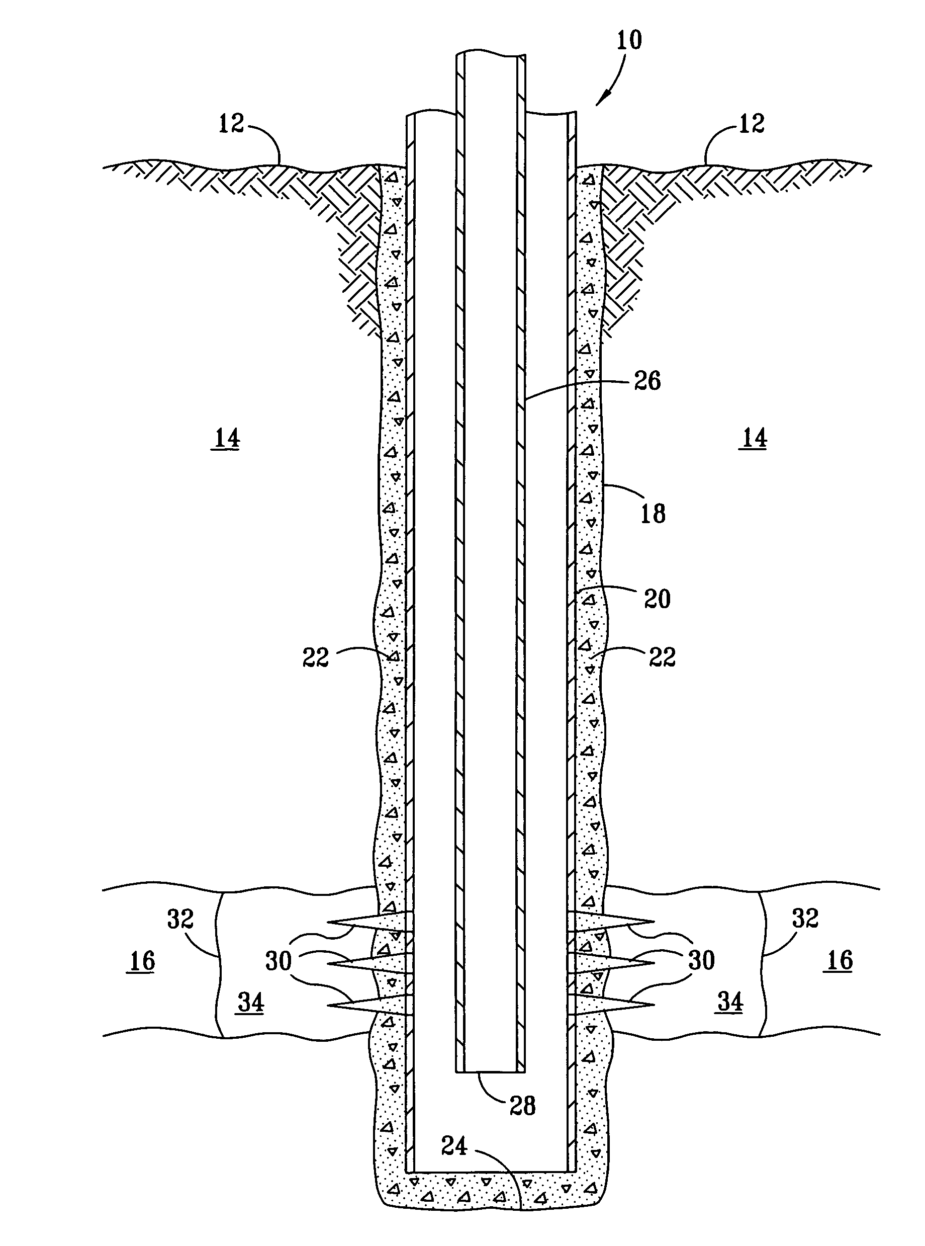
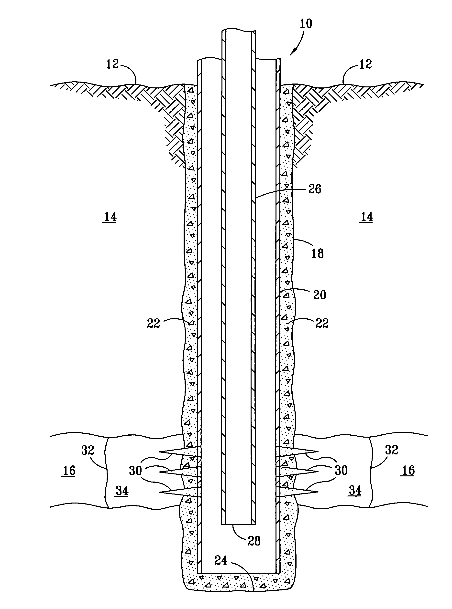
[0015]In the FIGURE a well 10 is shown extending from an earth surface 12 through an overburden 14 and penetrating a formation 16. The well comprises a wellbore 18, including a casing 20, which is cemented in place with cement 22. The casing extends to near a bottom 24 of the well. A tubing 26 is provided inside the casing for the production of fluids from subterranean formation 16. Perforations 30 are positioned through casing 20 in formation 16 to permit the flow of fluids from formation 16 into the casing. These fluids are then produced by pumping, natural flow from the formation or the like through the tubing 26 to the surface. A line 32 defines a near wellbore zone 34.

[0016]As well known to those skilled in the art, pumps, valves, and the like are used to achieve the flows as described in well 10. If well 10 is a water well, water can flow into casing 20 via perforations 30 for production by pumping upwardly through tubing 26. Even if tubing 26 and casing 20 are non-ferrous, it...


PUM

PropertyMeasurementUnit
weight percentaaaaaaaaaa

Abstract

A method and composition and system which for the oxidation, clean up, removal and control of iron and iron deposits in water and the removal of iron deposits and bacterial bio-films from surfaces in water systems. The composition contains sodium chlorite, sodium hypochlorite and citric acid.

Description

RELATED CASES[0001]This application is entitled to and hereby claims the benefit of the filing date of U.S. provisional application, 60 / 658,138 filed Mar. 3, 2005 by Greg D. Simpson and titled “Oxidation, Cleanup, Removal or Control of Fe and FeS Deposits.”FIELD OF THE INVENTION[0002]The present invention relates to the removal of iron deposits from surfaces in a water system. The field of the invention also contemplates the oxidation, clean up, removal and control of iron and iron sulfide deposits in water. The present invention also contemplates the removal of bacterial bio-films from surfaces in water systems.BACKGROUND OF THE INVENTION[0003]Many systems have been proposed and used to remove bacterial growth and the like from surfaces in a water system. Some systems, such as disclosed in U.S. Pat. No. 4,892,148 issued Jan. 9, 1990 to James A. Mason and U.S. Pat. No. 5,719,100 issued Feb. 17, 1998 to Zradnick, et al use sodium chlorite and citric acid to treat water. These two pat...

Claims


Application Information

Patent Timeline
Patent Type & Authority Patents(United States)
IPC IPC(8): C02F1/76
CPCC02F1/683C02F1/76E21B37/06C02F2101/101C02F2103/10C02F2303/20C02F2101/203
Inventor SIMPSON, GREG D.
Owner CHEMCAL INC
Why Eureka
Try Eureka