Supercharge Your Innovation With Domain-Expert AI Agents!

Optical module

a technology of optical modules and optical fibers, applied in the field of optical modules, can solve the problems of limiting miniaturization, affecting communication, and increasing costs, and achieve the effect of greatly reducing the error of interference from signals emitted by local stations

Inactive Publication Date: 2009-07-21
NEC CORP
View PDF13 Cites 1 Cited by
  • Summary
  • Abstract
  • Description
  • Claims
  • Application Information

AI Technical Summary

Benefits of technology

The present invention provides an optical module that prevents optical signals from a local station from coupling to the light-receiving element, reducing noise and improving communication. The optical module includes an optical path conversion means that guides optical signals in a different direction to the light-receiving element, ensuring that an image of the light-emitting spot does not overlap with the light-receiving surface. The optical path conversion means can include reflectors or differences in refractive indices. The optical module also includes a third optical waveguide with optical multiplexing / de-multiplexing means for transmitting and receiving optical signals. The invention prevents stray light from reaching the light-receiving surface and reduces errors due to interference from signals emitted by the local station.

Problems solved by technology

When it is incident on light-receiving element 202, the stray light devolves into noise on top of the original received optical signal and impedes communication.
Furthermore, since the configuration of light-receiving element 202 is intended for direct reception of optical signals emitted from the end face of transceiving optical waveguide 303, it has to be provided separately from optical waveguide substrate 101, which creates problems in terms of increased cost and limitations on miniaturization.

Method used


Image

  • Optical module
  • Optical module
  • Optical module

Examples


first embodiment

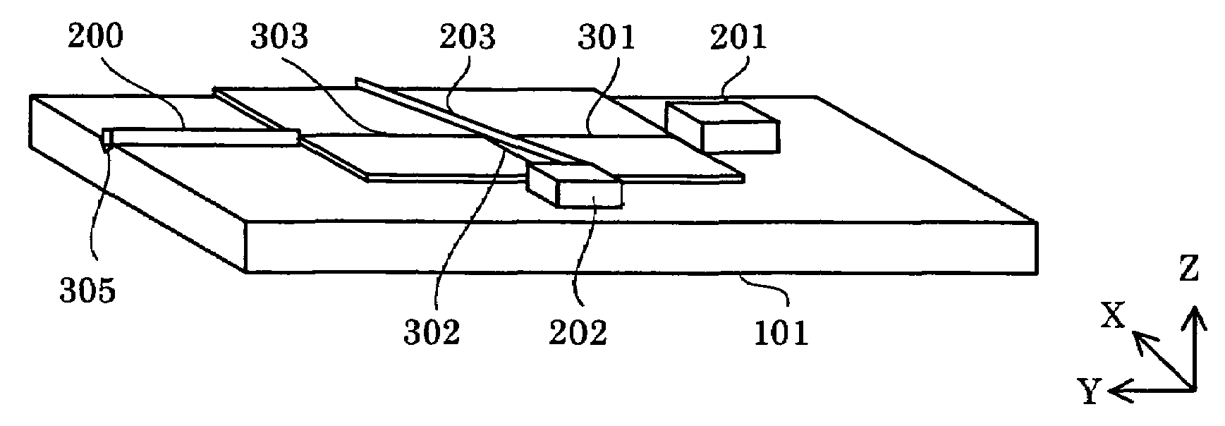
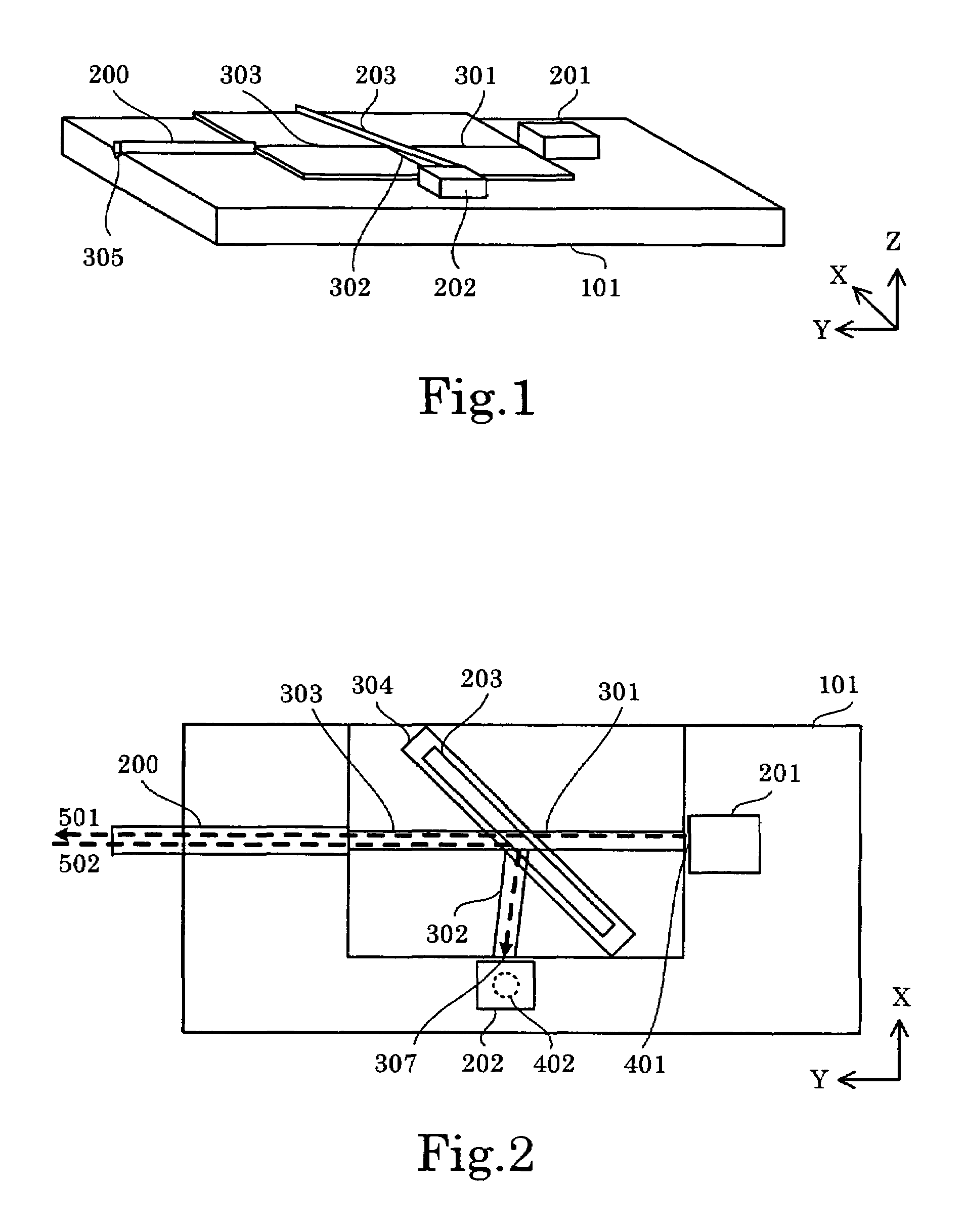
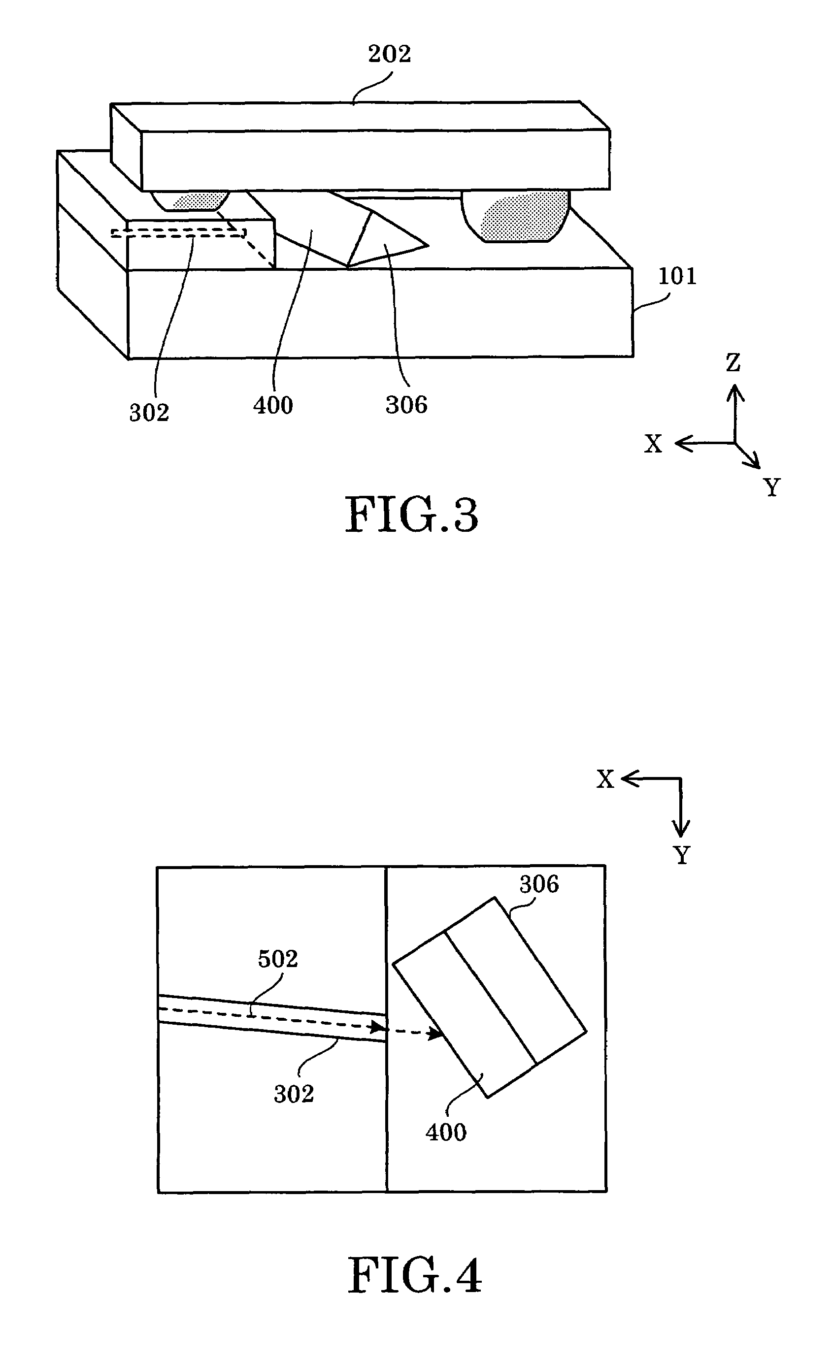
[0036]FIG. 1 through FIG. 4 illustrate the configuration of an optical module used in the present invention, with FIG. 1 showing a perspective view, FIG. 2 a plan view, FIG. 3 an enlarged view of the vicinity of the light-receiving element, and FIG. 4 a plan view of the vicinity of said portion without the light-receiving element.

[0037]The optical module comprises light-emitting element 201, transmitting optical waveguide 301 optically coupled to light-emitting element 201, light-receiving element 202, and receiving optical waveguide 302 guiding optical signals to light-receiving element 202, all of which are located on optical waveguide substrate 101, and furthermore, comprises transceiving optical waveguide 303 with optical fiber 200 optically coupled thereto and, as optical multiplexing / de-multiplexing means for outputting transmitted optical signals from transmitting optical waveguide 301 to transceiving optical waveguide 303 and guiding received optical signals coming in from t...

third embodiment

[0059]FIG. 8 is a plan view explaining the configuration of the optical module used in the present invention, FIG. 9 is an enlarged perspective view of optical path converter 306 and its periphery, and FIG. 10 is an enlarged plan view of optical path converter 306 and its periphery without light-receiving element 202. In this embodiment, a groove is formed in a portion of receiving optical waveguide 302 and the surface facing end face 307 of receiving optical waveguide 302 is machined into an inclined surface. A material of superior reflectance, e.g. gold, is deposited over a portion or all of the inclined surface in order to use its reflection as optical path converter 306. At such time gold is preferable as the metal deposited on the inclined surface. The reason for this is the ability to simultaneously form the electrical wiring of light-receiving element 202 and light-emitting element 201.

[0060]FIG. 11 is a perspective view illustrating the configuration of the optical module us...


PUM


Abstract

An optical module outputting transmitted optical signals from a light-emitting element to an optical fiber and guiding received optical signals arriving from the same optical fiber to a light-receiving element prevents transmitted optical signals originating from the light-emitting element of a local station from coupling to the light-receiving element, devolving into noise and impeding communication. Light-emitting element and light-receiving element are arranged in a positional relationship, whereby the optical axis of light-emitting element and the normal to light-receiving surface of light-receiving element are located in a spatially divergent relationship. Furthermore, it comprises optical path conversion elements which, along with guiding optical signals propagating along receiving optical waveguide to light-receiving surface of light-receiving element, ensures that the image of the light-emitting spot of light-emitting element projected onto a plane including light-receiving surface of light-receiving element does not overlap with light-receiving surface of light-receiving element.

Description

BACKGROUND OF THE INVENTION[0001]1. Field of the Invention[0002]The present invention relates to a device for carrying out optical communication via optical fibers. In particular, the present invention relates to an optical module for carrying out bidirectional transmission and reception of optical signals over a single optical fiber.[0003]2. Description of Related Art[0004]The development of communication technologies in recent years has resulted in the implementation of single-fiber bidirectional optical modules used for carrying out transmission and reception of optical signals over a single optical fiber. Small-sized, high-speed, inexpensive optical modules are in particular demand for “Fiber-to-the-home” (FTTH), in which household-oriented data communication services are provided by running fiber-optics to individual homes.[0005]FIG. 16 explains the configuration of a conventional bidirectional optical module. The optical module utilizes a waveguide type optical wavelength mult...

Claims


Application Information

Patent Timeline
Patent Type & Authority Patents(United States)
IPC IPC(8): G02B6/12G02B6/26
CPCG02B6/29368G02B6/4246G02B6/4202G02B6/423G02B6/4204
Inventor SUGIMOTO, TAKARA
Owner NEC CORP
Features
  • R&D
  • Intellectual Property
  • Life Sciences
  • Materials
  • Tech Scout
  • Unparalleled Data Quality
  • Higher Quality Content
  • 60% Fewer Hallucinations
Learn More