
Disk array device and path failure detection method thereof

a technology of path failure and array device, which is applied in the field of path failure detection method of disk array device, can solve the problems of path failure in both normal path and alternate path, inability to detect path failure in alternate path, and significant processing load of the host system, so as to reduce the burden of processing system for checking path failur

Inactive Publication Date: 2009-07-21
GOOGLE LLC
View PDF9 Cites 14 Cited by
  • Summary
  • Abstract
  • Description
  • Claims
  • Application Information

AI Technical Summary

Benefits of technology

The present invention provides a disk array device and a method for detecting path failures in a reliable and efficient way. The device includes a control unit connected to a host system via a path, a memory for storing control information, and a storage apparatus for storing data transmitted from the host system. The control unit has a transmission unit for controlling the transmission and reception of data between the host system and the storage apparatus based on the control information stored in the memory, and a determination unit for determining whether a failure occurred in the communication path. This allows for checking a path failure by transmitting a path check command to the host system and monitoring the response, reducing the processing load burden on the host system. The invention also provides a method for checking the communication path between the host system and the disk array device using control information stored in a memory and transmitting a path check command to the host system. This allows for effective prevention of a path failure in both the normal path and the alternate path, ensuring reliable data transmission and reception.

Problems solved by technology

Thus, the host system is required to issue the path check command, confirm the response from the disk array device, manage information regarding whether there is a path failure, notify the administrator upon the occurrence of a path failure and other matters, and, as a result, the processing load of the host system will be significant.
Nevertheless, with the conventional method of detecting a path failure, although it is possible to detect a path failure in the normal path since a path check command is issued from the host system to the disk array device, a path failure in the alternate path cannot be detected since it is not possible to access in advance the alternate path that is switched from the normal path upon a failure.
Thus, when a path failure occurs in the alternate path, this will mean that a path failure is occurring in both the normal path and alternate path when the path is switched from the normal path to the alternate path.
As a result, there is problem in that the reception of data from the host system or the transmission of data to the host system will be stopped.

Method used


Image

  • Disk array device and path failure detection method thereof
  • Disk array device and path failure detection method thereof
  • Disk array device and path failure detection method thereof

Examples


Embodiment Construction

[0025]An embodiment of the present invention is now described in detail with reference to the drawings.

(1) Configuration of Storage System According to Present Embodiment

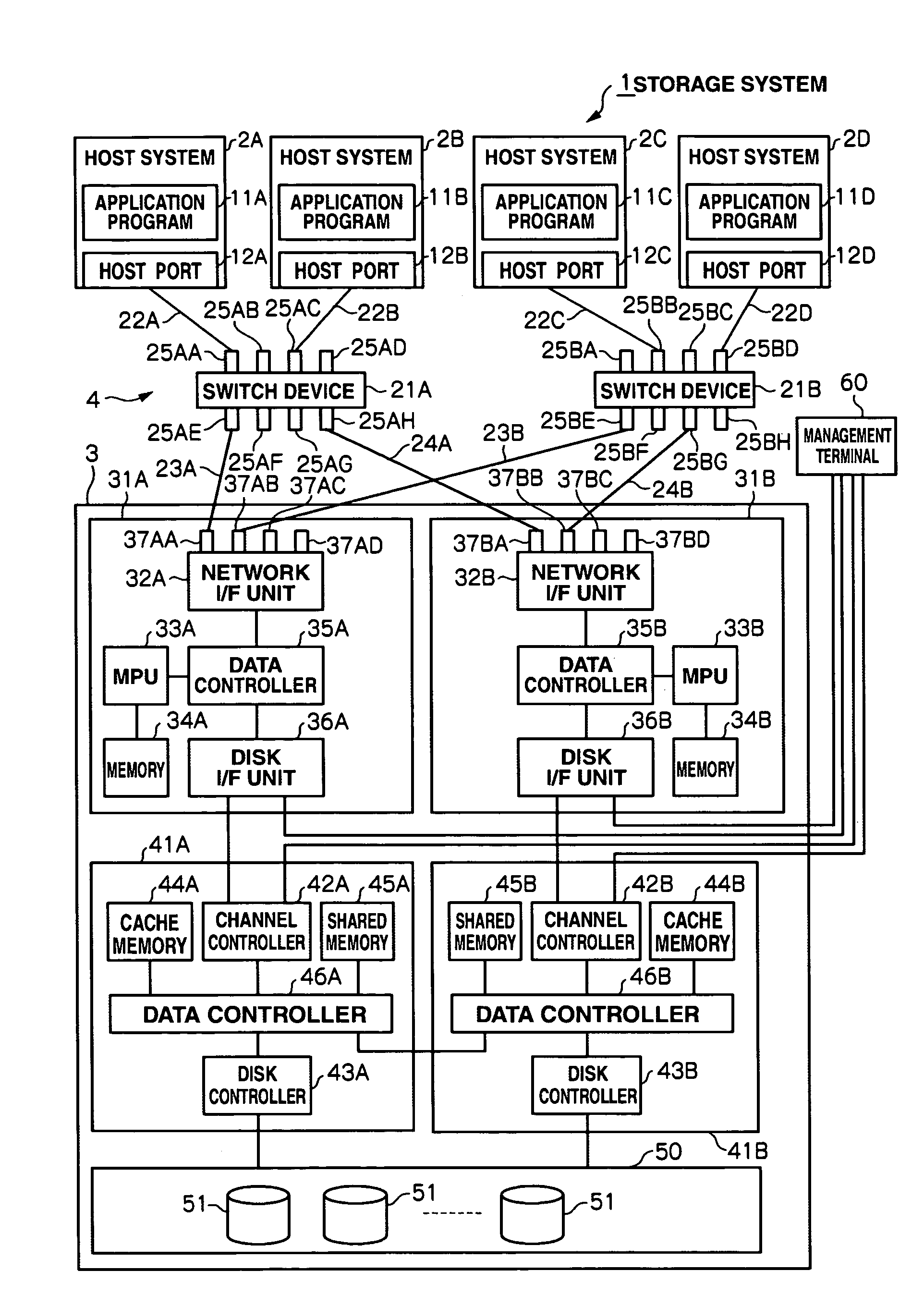
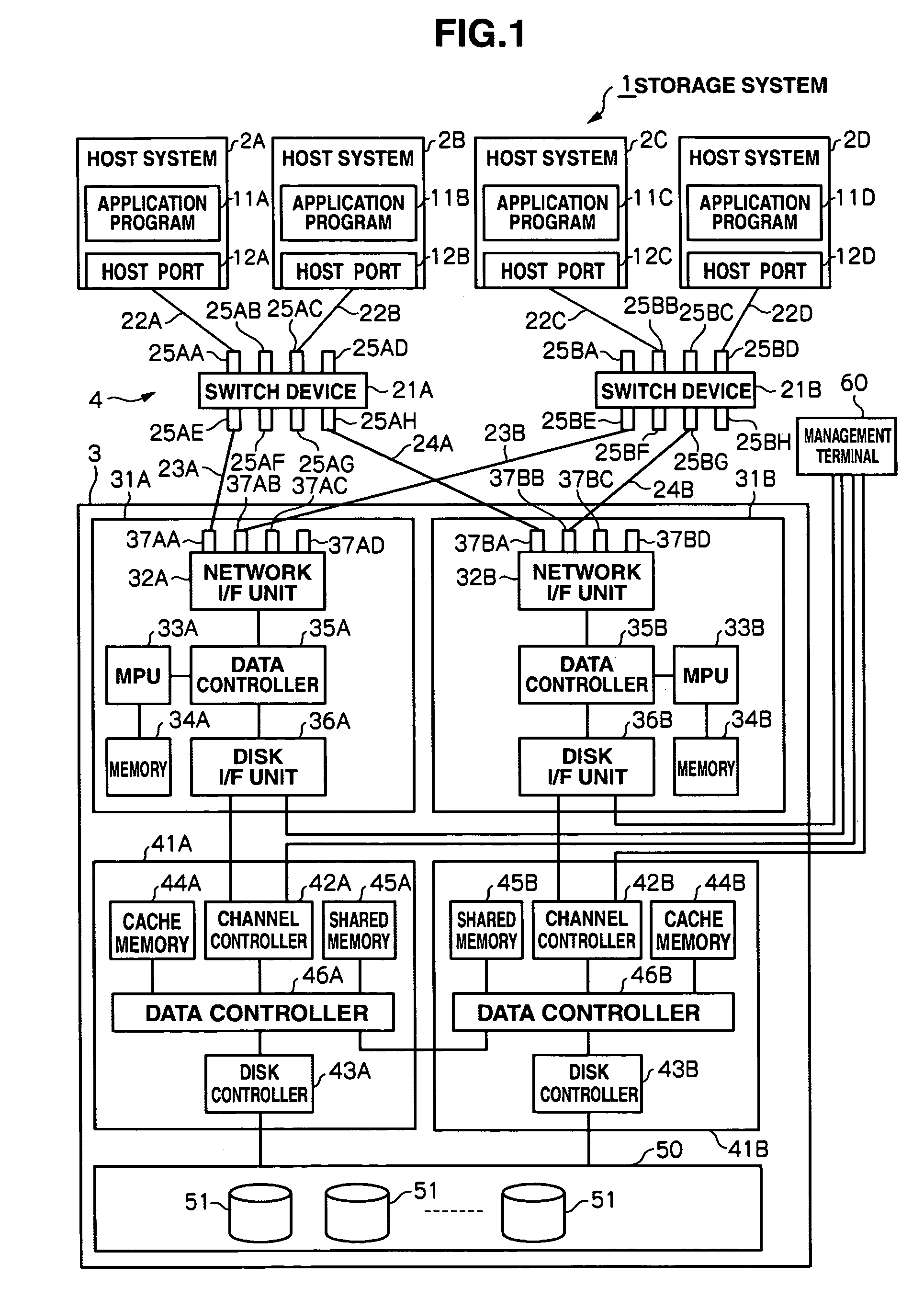
[0026]FIG. 1 shows the system configuration of a storage system 1 according to the present embodiment. This storage system 1 is configured by having a plurality of host systems 2 (2A to 2D) and a disk array device 3, and the host systems 2 being connected to the disk array device 3 via a network 4.

[0027]Each host system 2, for instance, is a host system having the likes of a CPU (Central Processing Unit) and memory, and specifically is a personal computer, workstation, mainframe computer or the like. Further, each host system 2, for example, is equipped with application programs 11 (11A to 11D), and host ports 12 (12A to 12D) for accessing the disk array device 3 via the network 4. Here, the application program 11, for instance, is an application program of a database or the like using a storage resource provided by...


PUM


Abstract

This disk array device includes a first control unit connected to a host system via a first path through which data is transmitted and received, a second control unit connected to the host system via a second path through which data is transmitted and received upon a failure, a memory storing control information, and a storage apparatus storing data transmitted from the host system; wherein the first control unit controls the transmission and reception of data between the host system and the storage apparatus conducted via the first path, and stores the control information used in the communication with the host system in the memory; and wherein the second control unit has a transmission unit for transmitting a command to the host system via the second path based on the control information used in the communication stored in the memory, and a determination unit for determining whether a failure occurred in the communication between the second control unit and the host system based on a response to the command.

Description

CROSS-REFERENCES TO RELATED APPLICATIONS[0001]This application relates to and claims priority from Japanese Patent Application No. 2005-322437, filed on Nov. 7, 2005, the entire disclosure of which is incorporated herein by reference.BACKGROUND OF THE INVENTION[0002]The present invention relates to a disk array device connected to a host system via network equipment such as a switch device, and to a path failure detection method thereof.[0003]Conventionally, a storage system which, by connecting a plurality of host systems and a plurality of disk array devices via network equipment such as a switch device, transmits an access request from a host system to a disk array device via network equipment, stores data in a physical disk of the disk array device according to an access request in such disk array device, or reads data from the physical disk is becoming widely prevalent.[0004]Here, for instance, a path failure between the host system and disk array device is detected by issuing ...

Claims


Application Information

Patent Timeline
Patent Type & Authority Patents(United States)
IPC IPC(8): G06F11/00
CPCG06F11/008
Inventor DOHI, HIRONORI
Owner GOOGLE LLC
Learn More