Top end stops for slide fastener

a technology of top end stop and fastener chain, which is applied in the direction of slide fasteners, press-button fasteners, snap fasteners, etc., can solve the problems of difficult to handle such a fastener tape, the front end of the fastener chain cannot be opened, and the processing of forming the notch grooves, etc., to facilitate the handling of the fastener tape

Active Publication Date: 2009-07-28
YKK CORP
View PDF12 Cites 17 Cited by
  • Summary
  • Abstract
  • Description
  • Claims
  • Application Information

AI Technical Summary

Benefits of technology

[0006]The present invention has been accomplished by solving the above-described problems. A main object of the invention is to provide top end stops for a slide fastener which allow a front end of a fastener chain to be opened to prevent occurrence of wrinkles in a fastener tape by a diamond of a slider, and which allows a coupling element and a top end stop to overlap each other easily, so that right and left fastener stringers are arranged neatly, thereby facilitating the handling of the fastener tape, and a single top end stop is processed by injection molding.
[0007]In addition to the above object, it is another object of the invention is to provide top end stop for a slide fastener in which a portion in the fastener chain where the top end stop and the coupling element overlap each other is provided on the fastener tape, and the overlapping portion is formed so as to be thinner than other portions, thereby achieving a presentable and accurate overlapping.
[0008]In addition, another object of the invention is to provide top end stops for a slide fastener achieving an accurate overlapping in which a portion of the top end stop where the top end stop and the coupling element overlap each other is formed on both front and rear surfaces of the top end stop, or on a same plane as a face of an engaging protrusion formed at a neck portion of the coupling element, or a same plane as a coupling face provided on the coupling element.

Problems solved by technology

Because the slide fastener shown in FIG. 9 comprises the elastomer coating layer 11′ provided on the surface of the fastener tape 2′, the fastener tape 2′ itself is provided with rigidity so that it is difficult to handle such a fastener tape.
Further, because the front ends of the sealing bodies 33′ are integrally connected to the locking block 31′, inconveniently, the front ends of the fastener chain cannot be opened.
Thus, the processing for forming the notch grooves 32′ is very troublesome, which is a problem to be solved.

Method used


Image

  • Top end stops for slide fastener
  • Top end stops for slide fastener
  • Top end stops for slide fastener

Examples


first embodiment

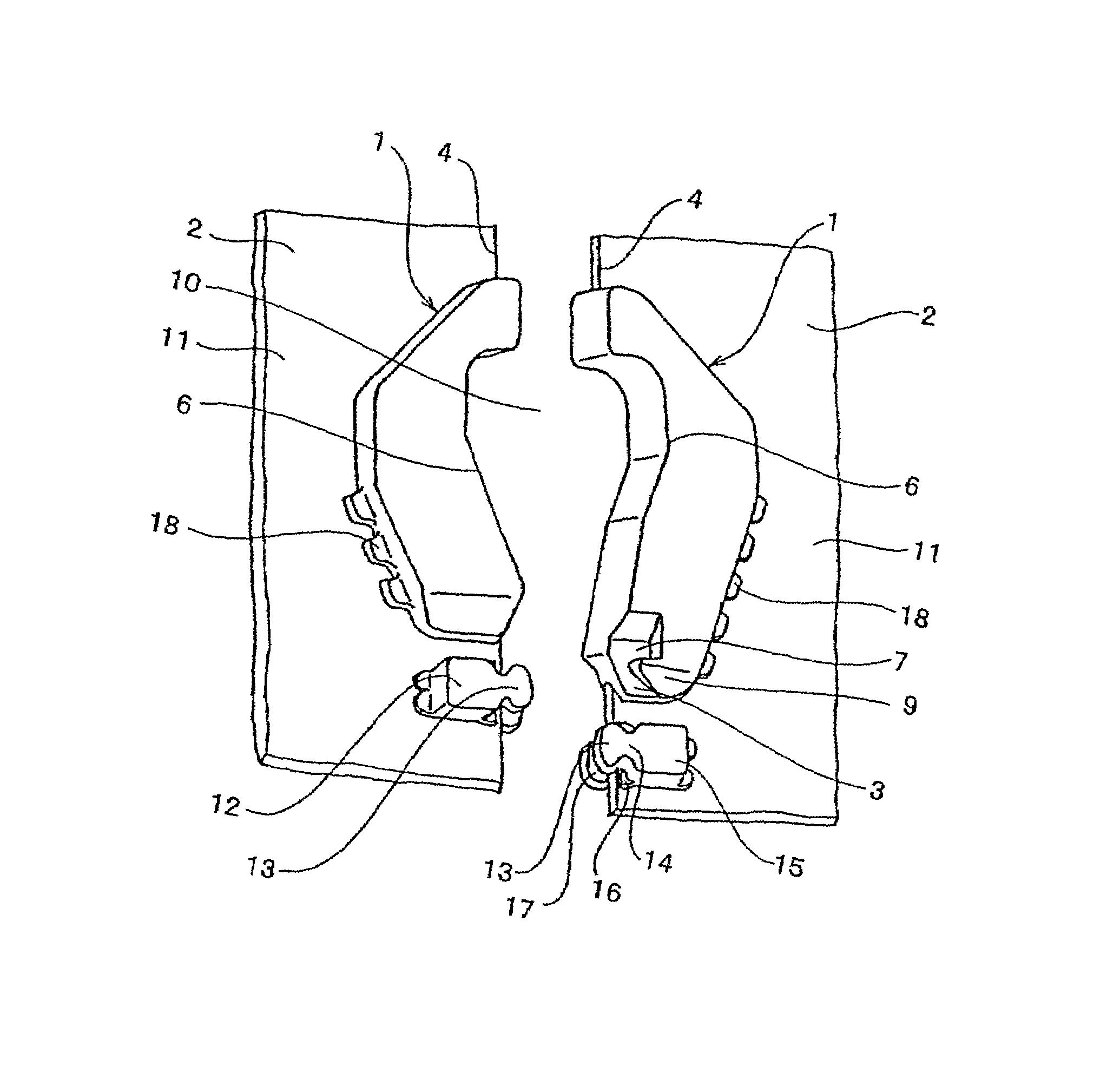
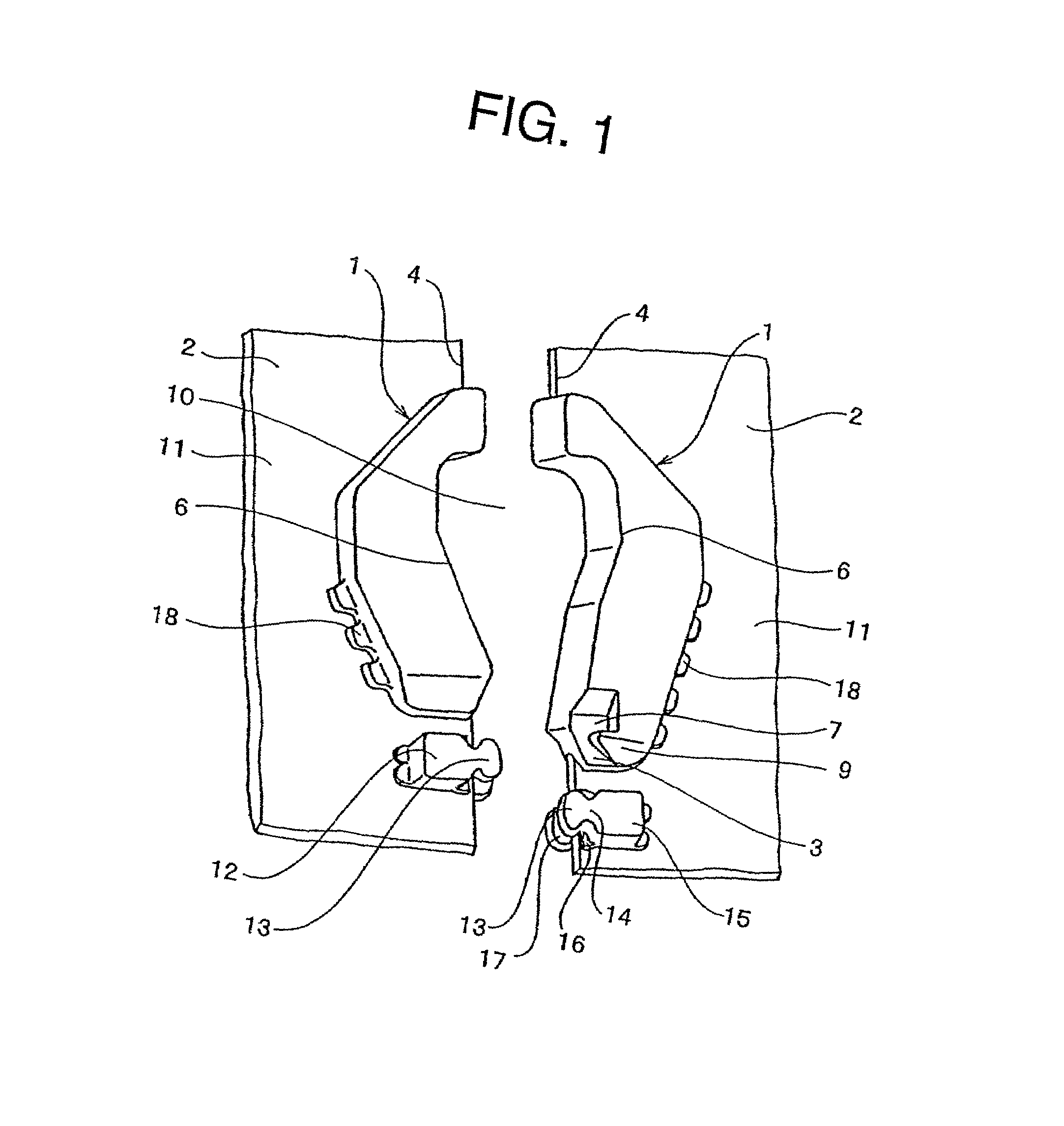
[0040]Top end stops for a slide fastener of the invention will be described. In the top end stops for the slide fastener according to a first embodiment of the invention shown in FIGS. 1 to 5, coating layers 11 are formed by coating both front and rear surfaces of each of the fastener tapes 2 in a fastener chain with synthetic rubber or thermoplastic elastomer so as to provide the fastener tapes 2 with waterproof property or water cutoff performance. Edge portions 4 of the fastener tapes 2 closely contact with each other, when the fastener is closed. A notch portion 5 having a substantially same size as that of the top end stop 1 is formed in the fastener tape 2 in order to form the top end stop 1 in an edge portion 4 of a side edge of the fastener tape 2, and the top end stop 1 is molded by injection molding by using the notch portion 5 with polyamide, polyacetal, polypropylene, polyethylene terephthalate or the like. Each of the top end stops 1 entirely provides a hook shape, and ...

second embodiment

[0046]Top end stops for a slide fastener according to a second embodiment of the invention shown in FIG. 6 will be described. Top end stops 1 in a fastener chain are formed so as to have the same configuration as that of the top end stops 1 of the first embodiment. The second embodiment is different from the first embodiment only in that no coating layer 11 is provided on any of front and rear surfaces of a fastener tape 2. The fastener tape 2 is formed by weaving or knitting, and a swelling core thread 8 is woven or knitted into an edge portion 4 on the side edge of the fastener tape 2 so as to swell the edge portion. A concave fitting groove 19 having the same thickness as that of an engaging protrusion 16 of a coupling element 12 can be fitted to an overlapping portion 3 formed at a bottom end of the top end stop 1. A front end of the overlapping portion 3 projects sideways compared with the edge portion 4 of the fastener tape 2, so that upper and lower coupling faces 17 of the f...

third embodiment

[0047]Top end stops for a slide fastener according to a third embodiment of the invention shown in FIGS. 7 and 8 will be explained. The top end stops 1 in a fastener chain of this embodiment is largely different from those of the above embodiments in that an overlapping portion 3 is provided only on a side of the rear surface of the fastener chain, although the appearance of the top end stops is substantially the same as that of the top end stops of the above embodiments. As for shapes in front and rear sides of a coupling element 12 which can use the overlapping portion 3, for example, the shape of a front half portion of the coupling element 12 on the front surface is formed into an elongated triangle while the shape of the front half portion on the rear surface is formed into a round head shape, i.e., a gourd shape, so that the coupling element 12 engages through a round-head-shaped coupling face 17 on the rear surface. Therefore, the overlapping portion 3 is provided on the rear...


PUM


Abstract

Various embodiments of top end stops for a slide fastener are made of resin and are each formed adjacent to an end portion of each of two rows of coupling elements provided along edge portions of a pair of fastener tapes. Each of the top end stops has a concave portion on an opposed face to the other top end stop, and each of the concave portions accomodate a slider therebetween when the slide fastener is colsed. A gap is formed between each top end stop and a coupling element disposed at the end portion of each row of the coupling elements, and an overlapping portion is formed in a bottom end of one of the top end stops, such that a coupling head of a mating coupling element is capable of overlapping the overlapping portion.

Description

BACKGROUND OF THE INVENTION[0001]1. Field of the Invention[0002]The present invention relates to atop end stop of a fastener chain, the fastener chain comprising coupling elements each of which formed of a single body of resin.[0003]2. Description of the Related Art[0004]Conventionally, for example, according to Japanese Utility Model Application Publication No. 63-13689, there have been fastener stringers 35′, in which a coating layer 11′ composed of elastomer such as rubber is provided on both front and rear surfaces of each of fastener tapes 2′ and the coupling elements 12′, fins made of the same material as that of the coating layer 11′ are provided between the respective coupling elements 12′ at edge portions of the fastener tapes 2′, and the fastener stringers 35′ are integrally connected to each other by a locking block 31′ at end portions of coupling element rows of the right and left fastener stringers 35′. In such fastener stringers 35′, the coupling elements 12′ and the l...

Claims


Application Information

Patent Timeline
Patent Type & Authority Patents(United States)
IPC IPC(8): A44B19/36
CPCA44B19/386Y10T24/2598Y10T24/2513Y10T24/2593A44B19/36A44B19/32
Inventor KUSAYAMA, MASAHIROMATSUMOTO, SATOSHITANAKA, RYO
Owner YKK CORP
Why Eureka
Try Eureka