Re-configurable impedance matching and harmonic filter system

a harmonic filter and impedance matching technology, applied in the field of communication devices, can solve the problems of harmonic filter circuit for low frequency band signals that is not desirable for high frequency band signals, too high insertion loss, and the low frequency band signal harmonic filter network does not work well in matching the high frequency band signal pa to the antenna switch impedance,

Active Publication Date: 2009-07-28
APPLE INC
View PDF10 Cites 46 Cited by
  • Summary
  • Abstract
  • Description
  • Claims
  • Application Information

AI Technical Summary

Problems solved by technology

In other words, the PA output impedance matching network for low frequency band signals does not work well in matching a high frequency band PA to antenna switch impedances.
If a typical single PA line-up is utilized for both frequency bands, an optimized low frequency signal band matching network will create significant mismatch for high frequency signal band operations and consequently, too high of an insertion loss.
Moreover, the harmonic filter circuit for low frequency band signals is not desirable for high frequency band signals because a low frequency band harmonic filter would almost completely reject the high frequency band transmitting signal.
Accordingly, current cellular telephones have a system utilizing two or more PA line-ups, which increases the cost and size of the cellular telephone.

Method used


Image

  • Re-configurable impedance matching and harmonic filter system
  • Re-configurable impedance matching and harmonic filter system
  • Re-configurable impedance matching and harmonic filter system

Examples


Embodiment Construction

[0011]The following detailed description is merely illustrative in nature and is not intended to limit the scope or application of possible embodiments. Furthermore, there is no intention to be bound by any expressed or implied theory presented in the preceding technical field, background, brief summary, or the following detailed description.

[0012]Various embodiments may be described herein in terms of functional and / or logical block networks and various processing steps. It should be appreciated that such block networks may be realized by any number of hardware, software, and / or firmware networks configured to perform the specified functions. For the sake of brevity, conventional techniques and systems related to semiconductor processing, packaging, and semiconductor devices are not treated in exhaustive detail herein.

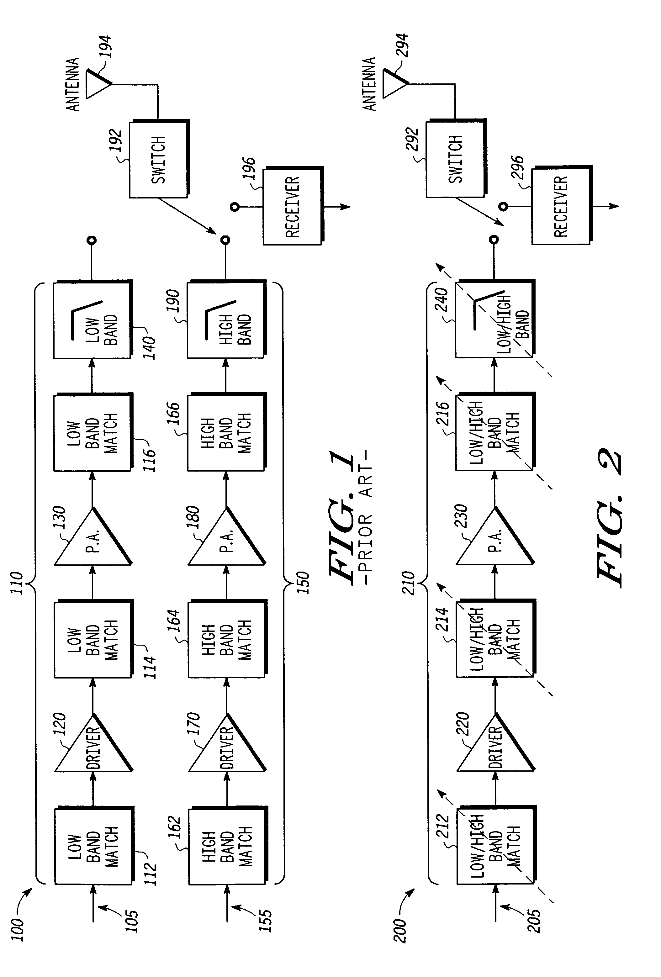
[0013]As discussed above, conventional communication devices (e.g., cellular telephones) are unsatisfactory in a number of respects. With reference to FIG. 1, for exa...


PUM


Abstract

Methods and apparatus are provided to enable a transceiver (200) or transmitter including a single PA line-up (210) to transmit signals having frequencies in two or more different frequency bands, and / or having two or more different modulation types, and / or having two or more different RF power levels. The single PA line-up includes at least one variable matching circuit (216) and a variable harmonic filter (240) to tune match and tune filter communication signals prior to transmission. The variable matching circuit and the variable harmonic filter each include at least one variable capacitive element (2160 and 2400) that switches ON / OFF depending on whether a low frequency signal or a high frequency signal is being transmitted. Each variable capacitive element includes separate direct current and radio frequency terminals to enable the single PA line-up to change signal modulation and / or RF power levels in addition to frequencies.

Description

FIELD OF THE INVENTION[0001]The present invention generally relates to communication devices, and more particularly relates to power amplifier line-ups in transceivers and transmitters.BACKGROUND OF THE INVENTION[0002]Many cellular telephones with, for example, a Global System for Mobile communications (GSM) modulation utilize two frequency bands: 824 MHz to 915 MHz and 1710 MHz to 1910 MHz. To utilize both frequency bands, cellular telephones include multiple power amplifier (PA) line-ups in typical radio frequency front-end modules. In GSM cellular telephones, there are typically two PA line-ups: one line-up for low frequency band signals (e.g., 824 megahertz (MHz) to 915 MHz), and one line-up for high frequency band signals (e.g., 1710 MHz to 1910 MHz).[0003]Separate line-ups for low frequency band signals and high frequency band signals is desirable because of the significant difference in the impedance matching networks and harmonic filter systems needed for each signal band. I...

Claims


Application Information

Patent Timeline
Patent Type & Authority Patents(United States)
IPC IPC(8): H04B1/04
CPCH04B1/0458H04B1/0067
Inventor LIU, LIANJUNMILLER, MELVY F.
Owner APPLE INC
Why Eureka
Try Eureka