VTOL personal aircraft

a personal aircraft and vertical take-off technology, applied in the direction of vertical landing/take-off aircraft, aircraft navigation control, transportation and packaging, etc., can solve the problems of aircraft having difficulty hovering and operating in a vtol mode, and clearly unsatisfactory for an aircraft, so as to increase the speed of air flowing and reliably execute vertical take-off and landing.

Inactive Publication Date: 2009-08-04
MILDE JR KARL F
View PDF5 Cites 8 Cited by
  • Summary
  • Abstract
  • Description
  • Claims
  • Application Information

AI Technical Summary

Benefits of technology

[0014]It is therefore an object of the present invention to provide a VTOL Personal Aircraft of the type described above which includes means for increasing the speed of the air flowing over the upper surface of each wing, which can hover and can reliably execute vertical take-offs and landings.

Problems solved by technology

However, such aircraft have difficulty hovering and operating in a VTOL mode unless facing into a relatively strong wind and / or operated at a high angle of attack into the wind.
This is clearly unsatisfactory for an aircraft which is intended to make frequent vertical take-offs and landings.

Method used


Image

  • VTOL personal aircraft
  • VTOL personal aircraft
  • VTOL personal aircraft

Examples


Embodiment Construction

[0033]The preferred embodiments of the present invention will now be described with reference to FIGS. 1-16 of the drawings. Identical elements in the various figures are designated with the same reference numerals.

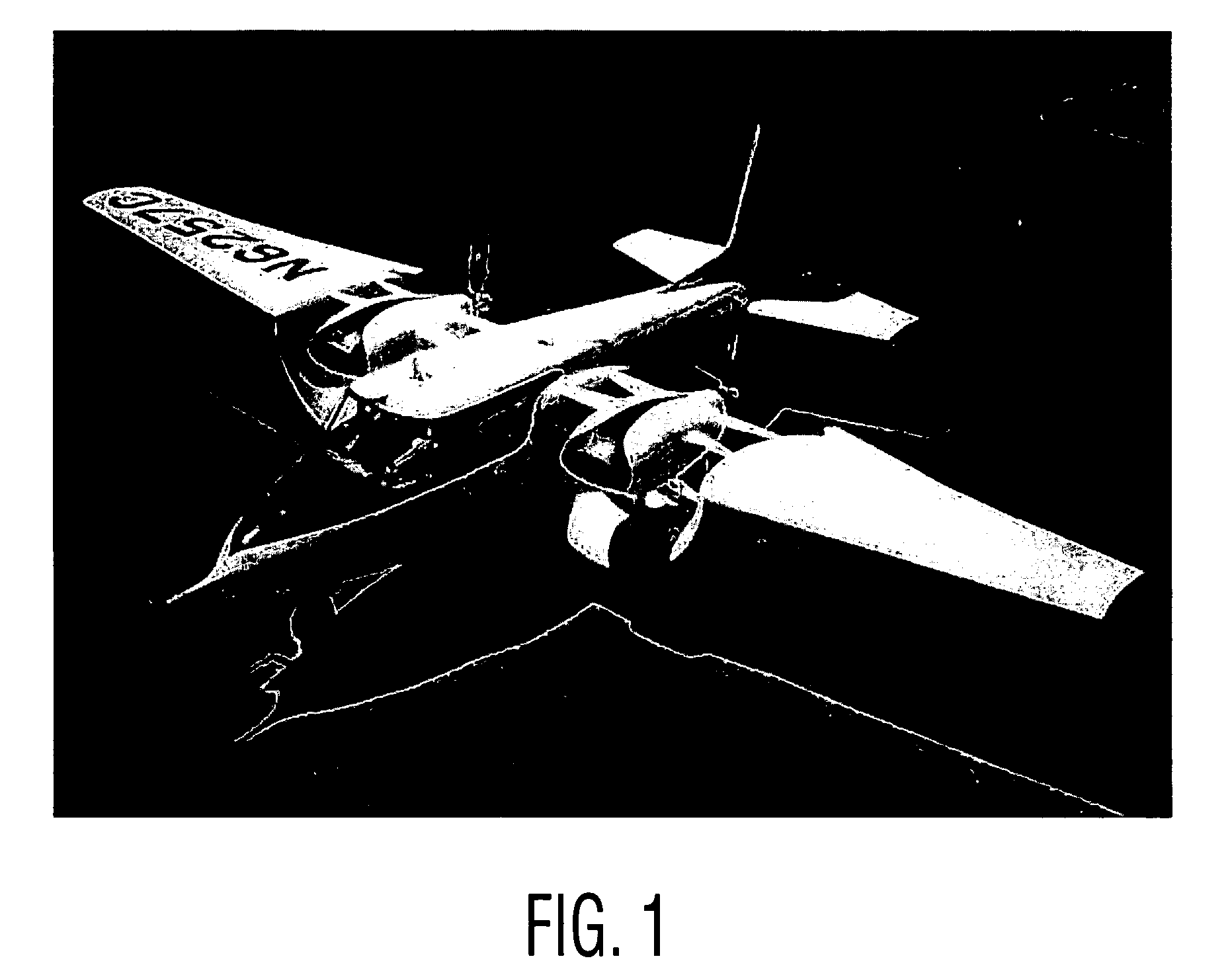
[0034]FIGS. 1-6 illustrate the well known Custer Channel Wing aircraft, as disclosed in the Custer patents, referred to above, and in the literature. Since these figures illustrate the well-known prior art, no further discussion thereof is believed to be necessary.

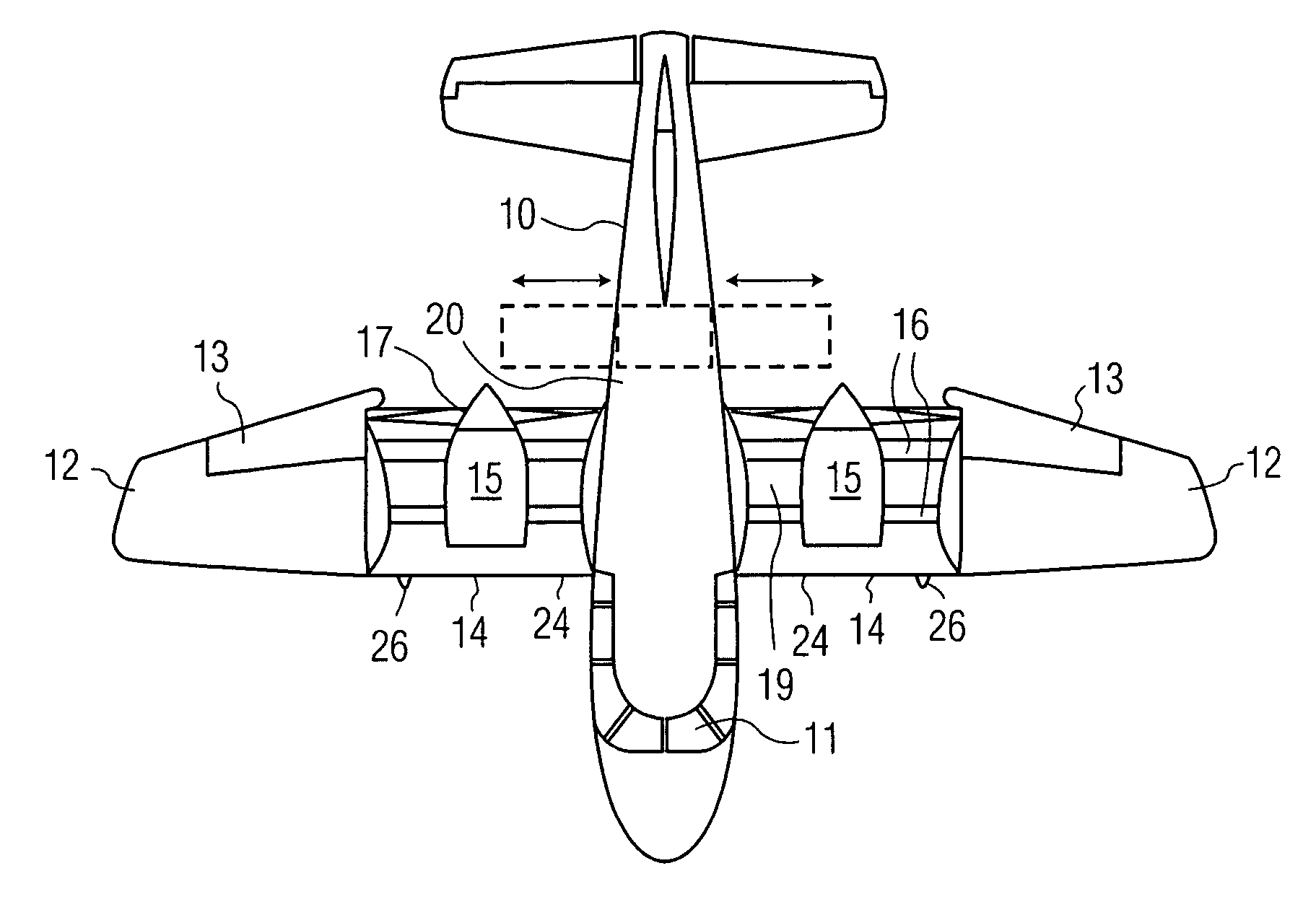
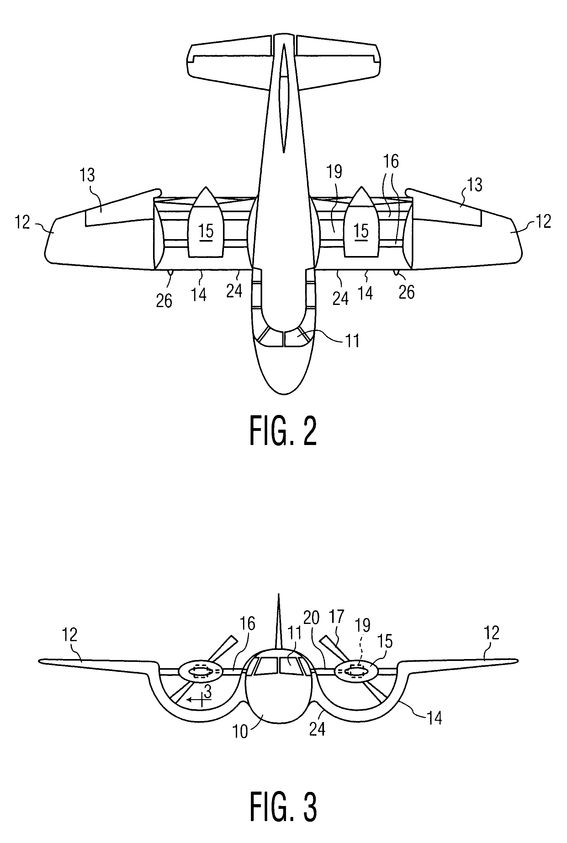
[0035]FIGS. 7, 8 and 9 illustrate, respectively, three different preferred embodiments of an air deflector according to the present invention for deflecting downward the airstream flowing over the upper surface of the wing. In FIG. 7, a single deflector panel is disposed on each side of the fuselage between the rear edge of each wing and the aircraft tail. This panel is hinged at the top so that it may be moved between the active position shown, at an angle of approximately 45° with respect to the horizontal, an...


PUM


Abstract

A vertical take-off and landing (VTOL) aircraft comprises (1) a fuselage having a front end, a rear end and two lateral sides, the fuselage defining a substantially horizontal central longitudinal axis of the aircraft; (2) an aircraft tail arranged at the rear end of the fuselage and including a rudder and an elevator on each side of the fuselage with movable surfaces for controlling the aircraft; and (3) a wing on each side of the fuselage having a front edge, a trailing edge and an upper surface extending from the front edge to the trailing edge. According to the invention, means are provided for increasing the speed of an airstream flowing over the upper surface of each wing, and an air deflector is disposed on each side of the fuselage between the trailing edge of each wing and the aircraft tail. These deflectors each have a deflection surface to deflect downward the airstream flowing over the upper surface of the wing to act as a “brake” to the forward motion of the aircraft and to provide additional lift so that the aircraft may hover.

Description

CROSS REFERENCE TO RELATED APPLICATION[0001]This application is related to and claims priority from U.S. patent application Ser. No. 11 / 229,157, filed Sep. 16, 2005, entitled “VTOL PERSONAL AIRCRAFT”, which, in turn, is a continuation-in-part of U.S. patent application Ser. No. 11 / 114,836, filed Apr. 26, 2005, entitled “VTOL PERSONAL AIRCRAFT”, which, in turn, is a continuation-in-part of U.S. patent application Ser. No. 10 / 242,036, filed Sep. 11, 2002, now U.S. Pat. No. 6,886,776. This application also claims priority from U.S. Provisional Patent Application Ser. No. 60 / 661,554, filed Mar. 14, 2005.BACKGROUND OF THE INVENTION[0002]This application relates to a vertical take-off and landing (VTOL) aircraft designed to carry a pilot and just a small number (e.g., less than ten) of passengers. Such an aircraft may be denominated a “PERSONAL AIRCRAFT”.[0003]The present invention further relates to a VTOL Personal Aircraft of the conventional type; that is, an aircraft having a central,...

Claims


Application Information

Patent Timeline
Patent Type & Authority Patents(United States)
IPC IPC(8): B64C9/00
CPCB64C3/385B64C5/16B64C9/32B64C39/066B64C29/0025B64C29/0066B64C39/005B64C23/02
Inventor MILDE, JR., KARL F.
Owner MILDE JR KARL F
Why Eureka
Try Eureka