Bicycle having a removable power assist module

a technology of power assist device and bicycle, which is applied in the direction of great wheels, self-drivers, and amusements. it can solve the problems of excessive wear and noise during operation, excessive noise during operation, and inability to easily add or remove the bicycle, so as to achieve the effect of efficient transmission of torque to the crank journal, minimal maintenance, and easy removal

Inactive Publication Date: 2009-08-04
GINGL MANFRED +1
View PDF16 Cites 29 Cited by
  • Summary
  • Abstract
  • Description
  • Claims
  • Application Information

AI Technical Summary

Benefits of technology

[0011]In another aspect, the present invention is a modular power assist device which can be readily added or removed from the bicycle without the need for tools, so that the bicycle can be manually operated in a normal manner when so desired without carrying the extra weight of the power assist apparatus.
[0012]A further objective of the present invention is to construct a power assist apparatus for a bicycle that efficiently transmits torque to the crank journal without excessive noise or gear tooth wear due to misalignment.
[0013]Another objective of the present invention is to construct a power assist apparatus which is composed of few parts, is of lightweight construction, is efficient, is durable and requires a minimum of maintenance.
[0014]Another objective of the present invention is to construct a smoothly operating, vibration free, direct drive, power assist apparatus for a bicycle.

Problems solved by technology

However, some people are deterred from using a bicycle due to the effort required to pedal up one or more inclines, or hills.
However, the prior art direct drive power assist devices for a bicycle have generally required complex gearing arrangements.
Upon removal of the wheel for maintenance, such as tire repair, precise reengagement of the direct drive device is difficult, leading to excessive wear and noise during operation.
Also, complex gearing arrangements are difficult to maintain in precise alignment when the bicycle encounters road bumps and holes.
Further, the prior art direct drive power assist devices for bicycles have not been designed to be readily removable from the bicycle to permit normal manual usage without the extra weight of the direct drive device.

Method used


Image

  • Bicycle having a removable power assist module
  • Bicycle having a removable power assist module
  • Bicycle having a removable power assist module

Examples


Embodiment Construction

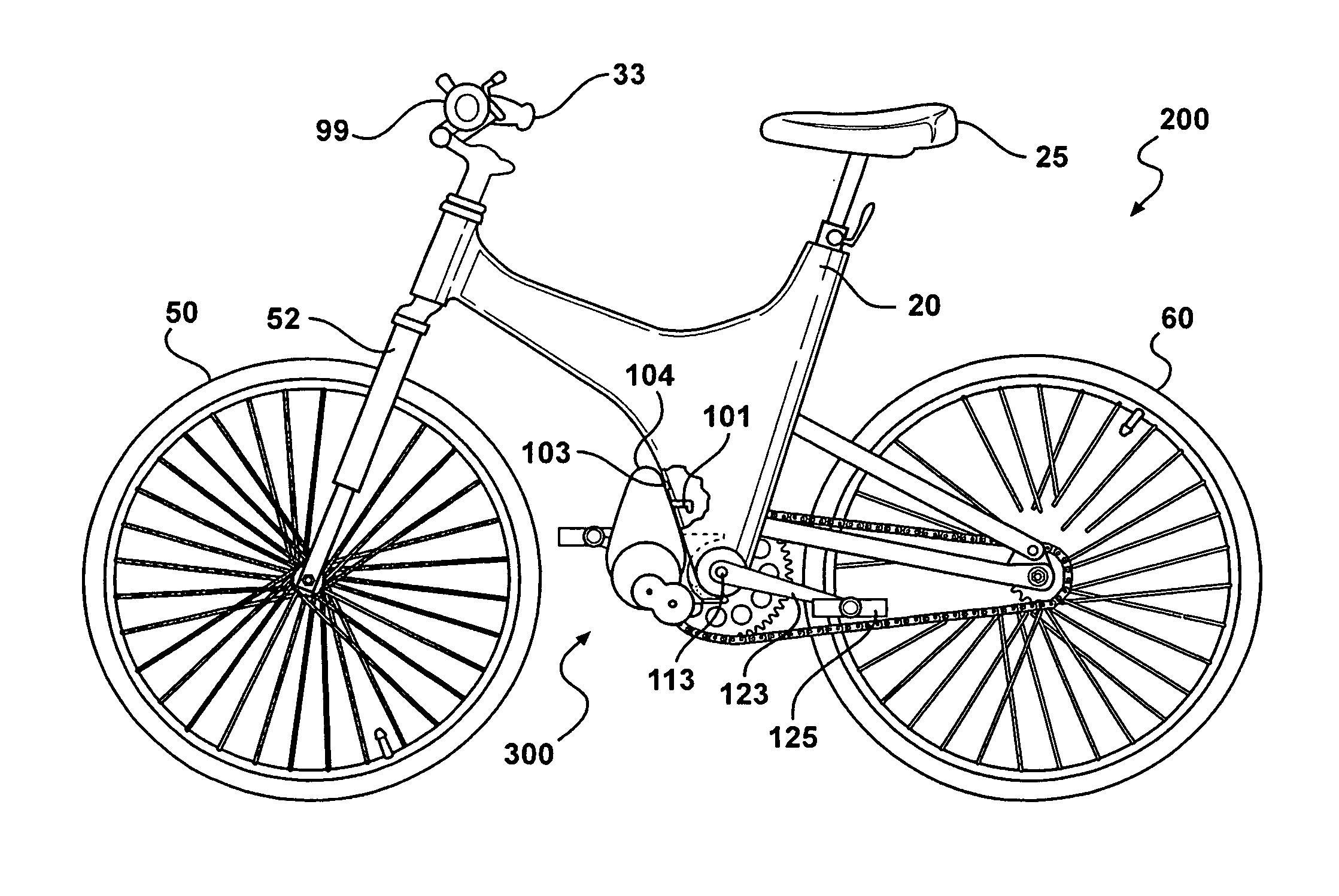
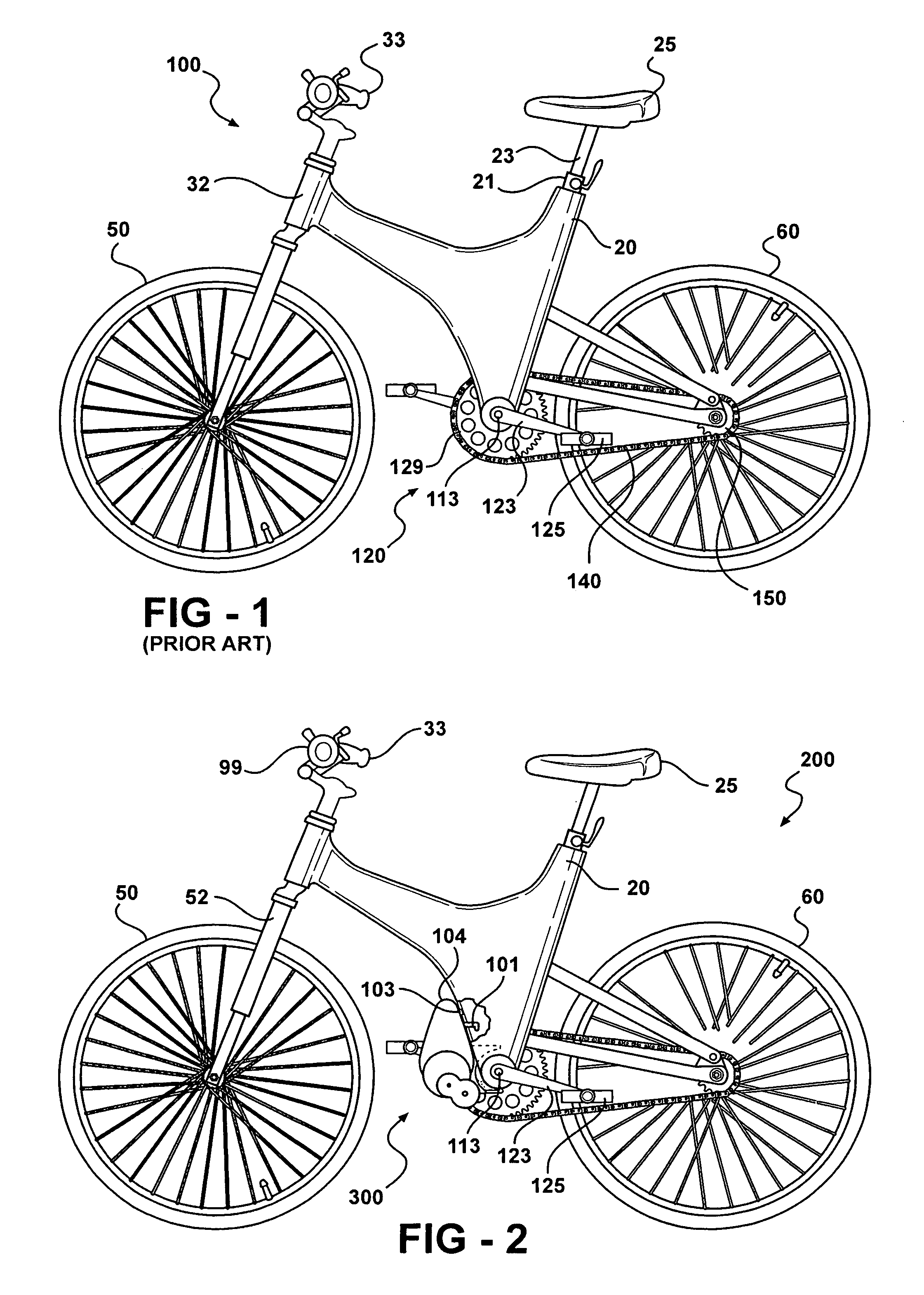
[0022]Referring to FIGS. 2-6, wherein like numerals indicate like or corresponding parts throughout the several views, the preferred embodiment of the invention includes a bicycle generally shown at 200 having a front steering wheel 50 and a rear wheel 60 attached to a frame 20.

[0023]The bicycle 200 has a crank arm 123 with a first end journalled to each side of a crank journal 113 and an opposite second end rotatably supporting a pedal 125. The crank journal 113 includes a front chain sprocket 129 having a plurality of circumferential teeth and a toothed rear sprocket 150 mounted to the rear wheel 60. A chain 140 is wrapped around each of the chain sprocket 129 and the rear sprocket 150 and in driving engagement with the teeth thereon whereby application of power by the rider on the pedals 125 rotates the crank journal 113 and propels the bicycle 200 as is commonly known in the art.

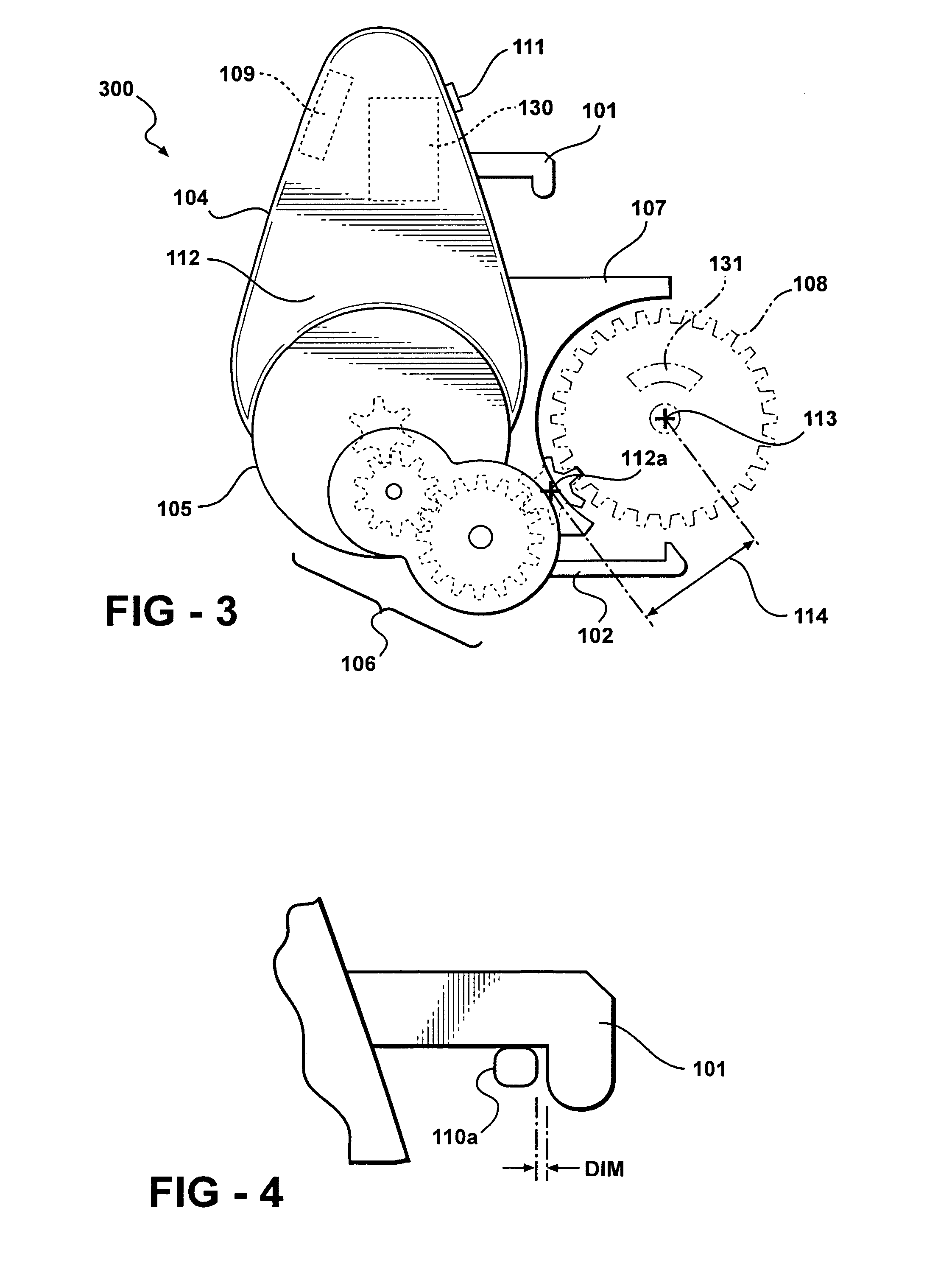
[0024]The subject invention relates to a self-contained electric or power assist module 300. The powe...


PUM


Abstract

A power assist module includes a battery powered motor mounted on a manually operated vehicle, such as a bicycle. The power assist module is fixedly mounted on the bicycle and can be easily removed without the need for tools, so that the bicycle can be manually operated in a conventional manner when so desired without carrying the extra weight of the power assist module. The power assist module includes a motor assembly which is operated through a gear reduction assembly to drive a crank drive gear mounted in conjunction with a crank arm of the bicycle.

Description

BACKGROUND OF THE INVENTION[0001]1. Field of the Invention[0002]The present invention relates to an electrically operated power assist apparatus for a manually operated vehicle, such as a bicycle, and, more particularly, to a new and novel construction of a power assist apparatus for a bicycle.[0003]2. Description of the Related Art[0004]By way of background, FIG. 1 illustrates a standard bicycle which includes a front steering wheel 50 and a rear wheel 60, which may be attached to a frame 20. The frame has a head tube 32 which journals a front fork 52 for steering via handles bars 33 by a rider of the bicycle 100. A seat tube 21 is carried by the frame 20 adjacent the rear wheel 60 and a seat post, upon which a saddle type seat 25 is positioned thereon to accommodate a rider, is slidably received in the seat tube 21 for adjusting the height of the seat 25.[0005]In the standard bicycle 100, a horizontally oriented crank journal 113 is positioned beneath the seat tube 21 for supporti...

Claims


Application Information

Patent Timeline
Patent Type & Authority Patents(United States)
IPC IPC(8): B62K11/04B62M6/55
CPCB62M6/55
Inventor SASNOWSKI, ALLANVENIER, FABIO
Owner GINGL MANFRED
Why Eureka
Try Eureka