Multi-region autofocus tool and mode

a multi-region, autofocus technology, applied in the direction of instruments, printers, cameras, etc., can solve the problems of limited alternatives, limited features and graphical user interface controls of video tools, especially dimensional metrology video tools, and limited alternatives for setting up video tool regions of interest (rois) and operating parameters during learn mode, etc., to achieve easy use and flexibility, and increase throughput

Active Publication Date: 2009-08-04
MITUTOYO CORP
View PDF9 Cites 69 Cited by
  • Summary
  • Abstract
  • Description
  • Claims
  • Application Information

AI Technical Summary

Benefits of technology

[0007]Currently, the users of precision machine vision inspection systems may spend a majority of their part-programming time setting up video tools and adjusting their parameters. Thus, even small improvements in their ease-of-use in comparison to their parameter customization capability, their GUI features, and other ergonomic factors, may be highly valued. In addition, even in small improvements inspection throughput are highly valued in industrial environments. Accordingly, the present invention is directed toward a novel and efficient “multi-region” autofocus video tool mode for configuring a multi-region autofocus video tool in an easy-to-use and flexible manner. In addition, the resulting multi-region autofocus tool may generally be operated to provide increased throughput compared to a conventional autofocus tool.
[0008]According to one feature of the invention, a system and method are provided which allow users to define and / or edit tool parameters for a plurality of autofocus ROIs with a reduced number of operations. The plurality of ROIs may be readily configured by the user to have different sizes, and / or overlap each other, etc. In one embodiment, these new video tool methods may be implemented as an alternative multi-region tool-type, or “tool mode,” that, along with a conventional tool-type, or mode, gives users a high level of control over autofocus tool set-up and operation alternatives with a simple and intuitive user interface.
[0017]According to one feature of the invention, a user may select an accuracy level for the autofocus calculations associated with multi-region set. This may be advantageous because the higher accuracy levels require the images used for autofocus analysis to be more closely spaced, and may require more calculations. Thus, if the user judges that lower accuracy levels are sufficient, the throughput may be increased.

Problems solved by technology

The currently available features and graphical user interface (GUI) controls for video tools, and particularly dimensional metrology video tools, are limited.
In particular, alternatives for setting up video tool regions of interest (ROIs) and operating parameters during learn mode, or manual mode, are limited.
Existing alternatives may be difficult to adapt for efficient use with different applications or workpieces.
Existing user interfaces may be difficult for users to understand intuitively, making user learning and retention difficult.

Method used


Image

  • Multi-region autofocus tool and mode
  • Multi-region autofocus tool and mode
  • Multi-region autofocus tool and mode

Examples


Embodiment Construction

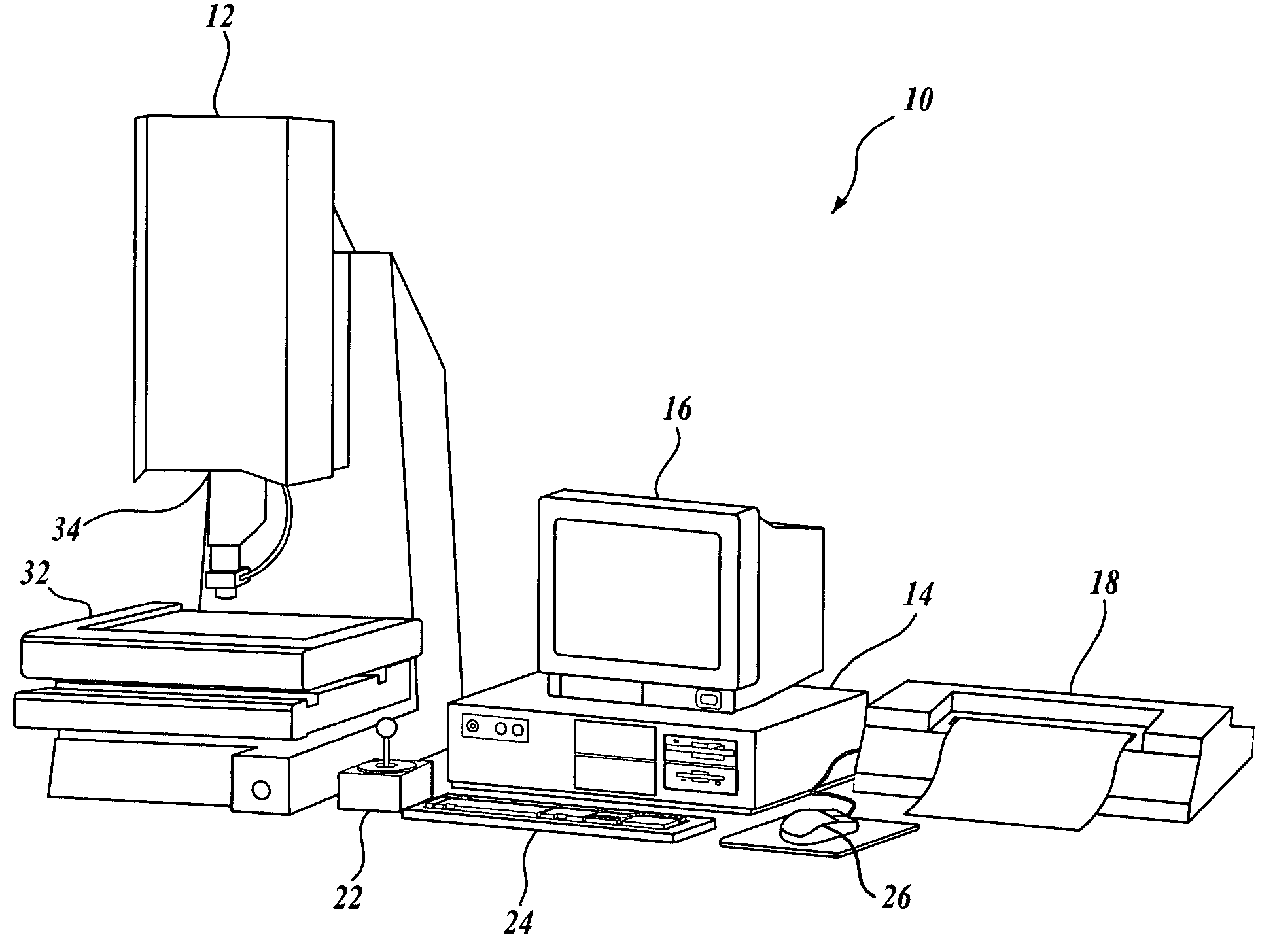
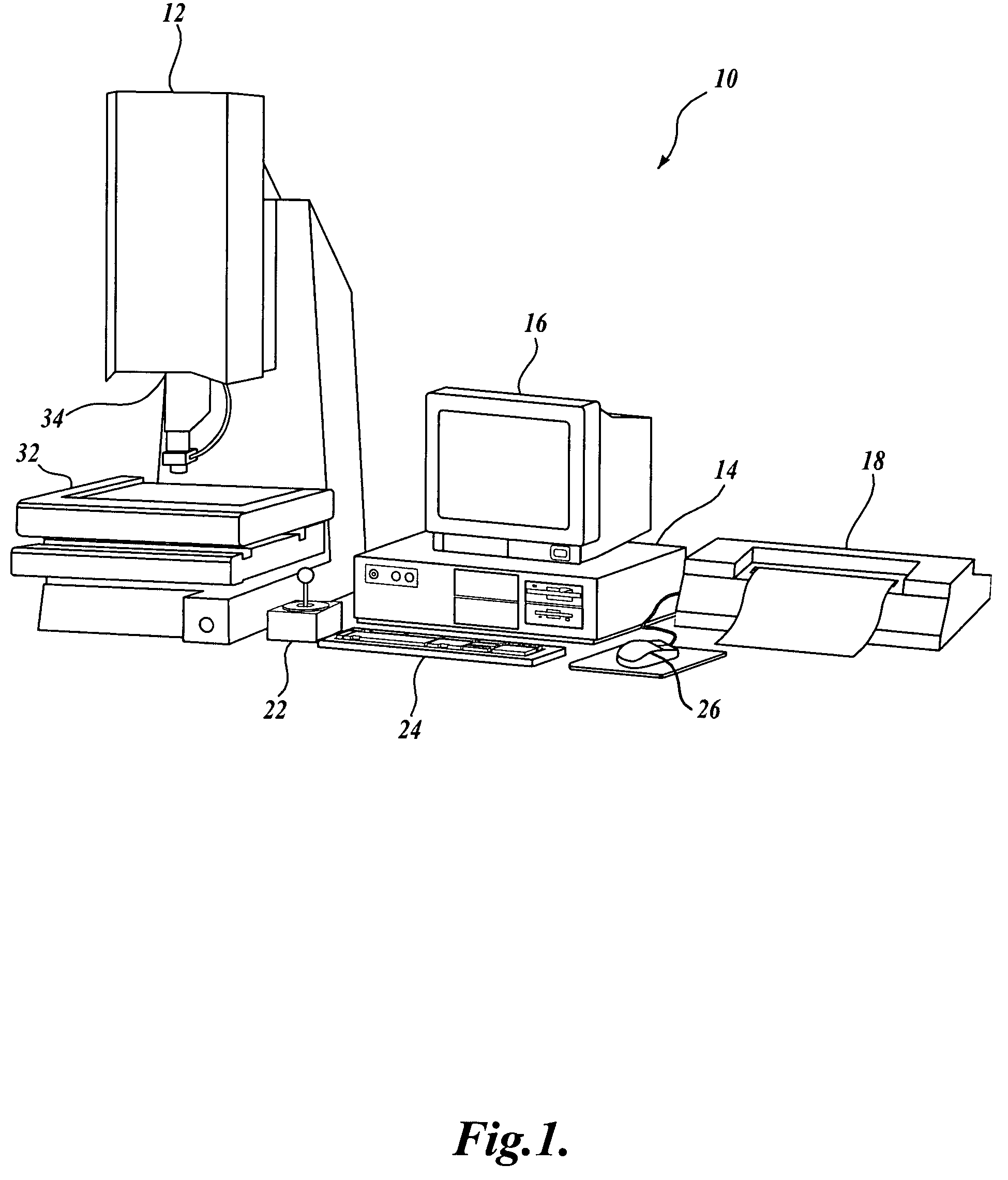
[0027]FIG. 1 is a block diagram of one exemplary machine vision inspection system 10 usable in accordance with the present invention. The machine vision inspection system 10 includes a vision measuring machine 12 that is operably connected to exchange data and control signals with a controlling computer system 14. The controlling computer system 14 is further operably connected to exchange data and control signals with a monitor or display 16, a printer 18, a joystick 22, a keyboard 24, and a mouse 26. The monitor or display 16 may display a user interface suitable for controlling and / or programming the operations of the machine vision inspection system 10.

[0028]The vision measuring machine 12 includes a moveable workpiece stage 32 and an optical imaging system 34 which may include a zoom lens or interchangeable lenses. The zoom lens or interchangeable lenses generally provide various magnifications for the images provided by the optical imaging system 34. The machine vision inspect...


PUM


Abstract

A system and method are provided for a “multi-region” autofocus video tool-type or mode within a machine vision inspection system. The user may efficiently define multiple regions of interest that are grouped as a “multi-region” set. The autofocus operations for the multi-region set are defined with a shared set of autofocus parameters. The same set of autofocus images may be used for the autofocus operations of the multi-region set. The user may conveniently also define individual autofocus regions of interest, defined with individual autofocus parameters, within the same field of view. Various user interface features allow a user to conveniently change between the individual autofocus tool-type or mode and the multi-region autofocus tool-type or mode.

Description

FIELD OF THE INVENTION[0001]The invention relates generally to machine vision inspection systems and, more particularly, to video metrology tool modes and tools usable to define inspection operations for such systems.BACKGROUND OF THE INVENTION[0002]Precision machine vision inspection systems (or “vision systems” for short) can be utilized to obtain precise dimensional measurements of inspected objects and to inspect various other object characteristics. Such systems may include a computer, a camera and optical system, and a precision stage that is movable in multiple directions so as to allow the camera to scan the features of a workpiece that is being inspected. One exemplary prior art system that is commercially available is the QUICK VISION® series of PC-based vision systems and QVPAK® software available from Mitutoyo America Corporation (MAC), located in Aurora, Ill. The features and operation of the QUICK VISION® series of vision systems and the QVPAK® software are generally d...

Claims


Application Information

Patent Timeline
Patent Type & Authority Patents(United States)
IPC IPC(8): G06K9/00
CPCG03B13/36G02B7/28G01B11/0608
Inventor YU, DAHAISAYLOR, BARRY EUGENETESSADRO, ANA M.
Owner MITUTOYO CORP
Why Eureka
Try Eureka