Deep hole boring head and deep hole boring method for boring a production piece

a production piece and boring head technology, applied in the field of deep hole boring head and deep hole boring method for boring production pieces, can solve the problems of boring head seizing, virtually impossible, and unsuitable boring heads for titanium (ti) pieces, so as to prevent any sticking phenomenon, improve the effect of accuracy and low cos

Active Publication Date: 2009-08-11
SAFRAN LANDING SYSTEMS
View PDF23 Cites 30 Cited by
  • Summary
  • Abstract
  • Description
  • Claims
  • Application Information

AI Technical Summary

Benefits of technology

[0014]The presence of the pilot drill bit, or centering bit, makes it possible to dispense with the presence of the guide pads and the problems associated with the titanium sticking to these pads. Consequently, the boring torque necessary to rotate the head during boring is sufficiently low so as to be able to be developed by machines widely used for boring materials other than titanium. In addition, the guidance obtained with the aid of the bit makes it possible to obtain good geometry of the hole and in particular to limit the deviations relative to the boring axis.
[0016]These pads should not be confused with the guide pads used in the prior art, because these pads in no way guide the boring head, the latter function rather being entirely performed by the pilot drill bit. The pads mounted on the boring head of the invention are useful once boring is complete, as the boring head is being removed from the hole made, and prevent the outer lateral edge of the cutting edge furthest from the central axis of the boring head from deeply scoring the walls of this hole. For this purpose, these pads are positioned on the body of the boring head so that this head can press on at least one of these pads as it is being removed. The weight of the boring head may therefore be distributed between the pad and the cutting edge, so that any pressure exerted by the cutting edge on the walls of the hole is lessened and the score marks made may be easily rectified during a subsequent machining step. These pads may also be useful in the event of breakage of one of the elements of the cutting head (usually one of the cutting elements forming the said cutting edges), to limit the zones of contact between the head and the walls of the hole bored and thus protect these walls.
[0017]This difference of functionality between the pads of the invention and the known guide pads also means that different materials are used and that the pads of the invention protrude only by a small distance from the periphery of the body of the boring head, which makes it possible to prevent any sticking phenomenon. The pads of the invention are made for example of bronze, a low cost material so that their replacement does not generate major expenditure.

Problems solved by technology

However, the boring heads known to date are unsuitable for boring titanium (Ti) pieces.
Specifically, the titanium adheres to the guide pads, which causes the boring head to seize and it then becomes virtually impossible with the machines currently used in the boring field to develop a sufficiently high boring torque to continue rotating the head.
Furthermore, premature wear of the guide pads is noted, which necessitates frequent replacement of the pads, while their price is high due to their specialist nature and the materials they are made of.
Finally, because of these unsatisfactory boring conditions, the geometry of the hole made is so bad (in particular, significant deviations are observed relative to the boring axis) that it is very difficult, even impossible, to rectify it by machining.
In addition, this subsequent machining step is made difficult by the presence of the carbide particles originating from the guide pads.

Method used


Image

  • Deep hole boring head and deep hole boring method for boring a production piece
  • Deep hole boring head and deep hole boring method for boring a production piece
  • Deep hole boring head and deep hole boring method for boring a production piece

Examples


Embodiment Construction

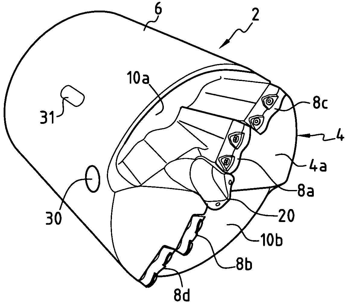
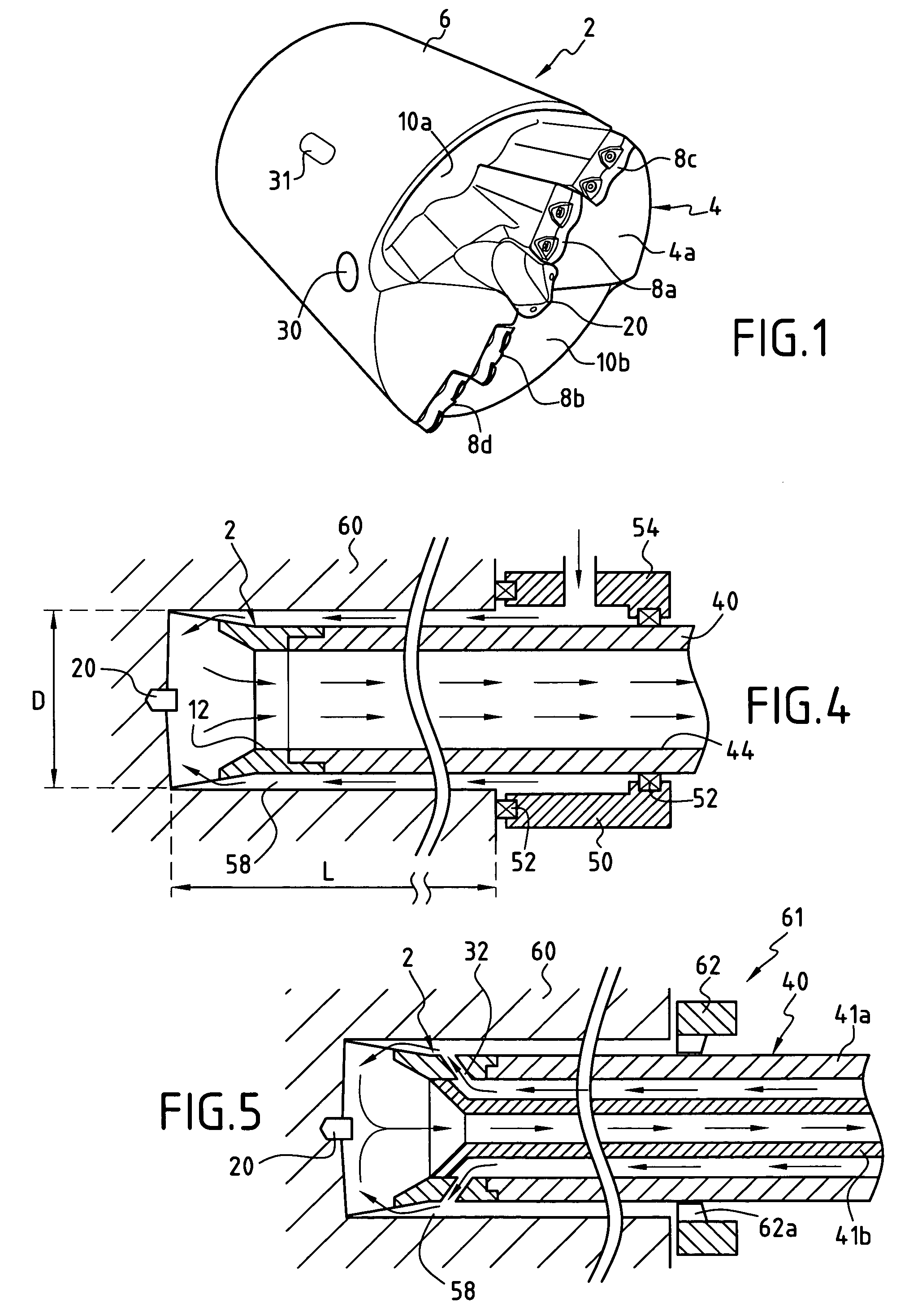
[0028]With reference to FIGS. 1, 2, 2a and 3, a description will now be given of an example of a boring head according to the invention.

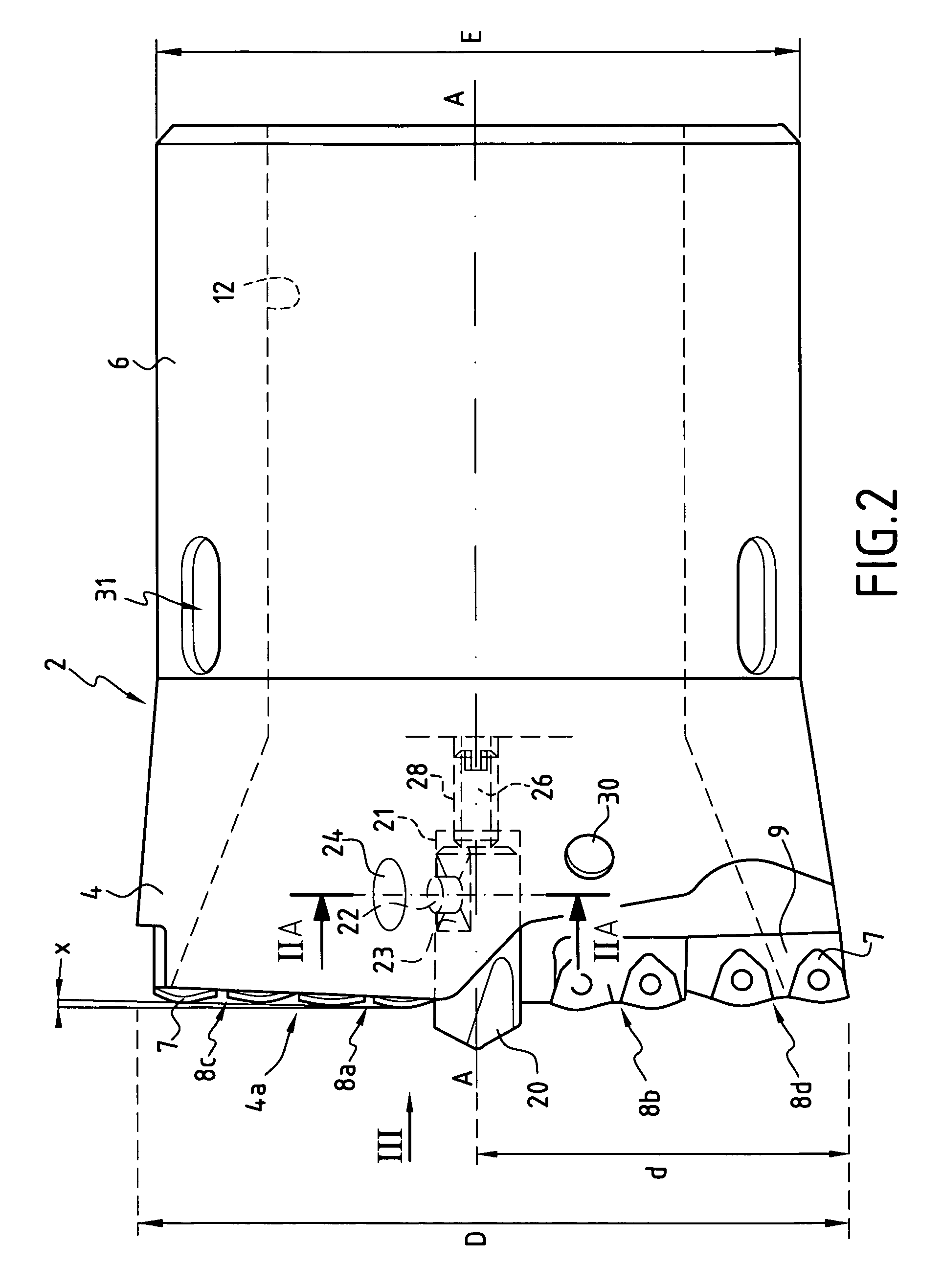
[0029]According to this particular embodiment, the boring head comprises a body 2 which has a front part 4 and a rear part 6. This boring head is intended to be rotated about the central axis A-A. The weight of the boring head is distributed so that the centre of gravity of this piece corresponds to the central axis A-A of rotation, which prevents any imbalance.

[0030]The general shape of the body 2 has a symmetry of revolution relative to the central axis A-A. More precisely, the front part 4 of the body 2 has a generally frustoconical shape widening towards the front, and the rear part 6 has the general shape of a hollow cylinder of external diameter E.

[0031]The front face 4a of the front part 4 usually has at least one cutting edge formed by at least one cutting tip mounted on the front part 4. In the example, the front face 4a has four cutting ed...


PUM

PropertyMeasurementUnit
diameteraaaaaaaaaa
diameteraaaaaaaaaa
diameteraaaaaaaaaa

Abstract

A deep hole boring head is provided which is capable of rotating about a central axis, a body whose front part has at least one cutting edge followed by a recess which leads to a duct inside the body, this duct allowing the chips formed during the boring to be cleared away rearwards, and includes at a front end thereof and at a center portion thereof a pilot drill bit capable of guiding the head during boring. Use for the boring of a production piece is made of titanium, the ratio L / D between the depth L of the hole bored and the diameter D of the latter being greater than or equal to 10, and the diameter D being greater than or equal to 65 mm.

Description

BACKGROUND OF THE INVENTION[0001]1. Field of the Invention[0002]The present invention relates to an improved deep hole boring head and a deep hole boring method for boring a production piece, and more particularly a production piece made of titanium.[0003]2. Discussion of the Background[0004]Deep hole boring differs from shallow hole boring, or from drilling, by the L / D ratio between the length L and the diameter D of the hole to be made. Thus, deep hole boring in the present specification means a boring method used to make holes having an L / D ratio greater than or equal to 10. With such an L / D ratio, it is particularly necessary to clear away the chips cut from the production piece during boring.[0005]Also, it will be noted that the invention is more particularly intended for boring large diameter holes, usually greater than 40 mm and, preferably, greater than or equal to 65 mm.[0006]Deep hole boring tools are already used for boring steel alloy pieces, such as 300M and 4340M alloy...

Claims


Application Information

Patent Timeline
Patent Type & Authority Patents(United States)
IPC IPC(8): B23B51/06B23B51/04
CPCB23B51/048B23Q11/006B23B2222/88B23B2251/603Y10T408/9065Y10S408/705Y10T408/455B23B51/0493B23B51/063
Inventor BISCAY, ALBERT
Owner SAFRAN LANDING SYSTEMS
Why Eureka
Try Eureka