Waterproof structure and waterproof method for wire connecting part

a technology of waterproof structure and connecting part, which is applied in the direction of connection contact member material, cable junction, coupling device connection, etc., can solve the problems of low work efficiency, corrosion of cores and pressure terminals, etc., and achieve low viscosity and efficient wrapping

Active Publication Date: 2009-08-11
SUMITOMO WIRING SYST LTD
View PDF32 Cites 30 Cited by
  • Summary
  • Abstract
  • Description
  • Claims
  • Application Information

AI Technical Summary

Benefits of technology

[0033]As described above, according to the present invention, waterproofing is performed by wrapping the foamed sheet impregnated with the silicone around the connecting part of the electric wires and filling the silicone in the clearances between the cores. In addition, the foamed sheet is capable of absorbing the silicone which has dropped or oozed therefrom. Therefore it is unnecessary to leave the silicone until it solidifies and possible to efficiently perform a work of wrapping the foamed sheet around the electric wires.
[0034]Further because the foamed sheet prevents the drop or oozing of the silicone, it is possible to use the silicone having a low viscosity as a waterproof agent and thus fill the silicone in a large number of clearances between the cores by securely allowing the silicone to permeate thereinto.

Problems solved by technology

When the connecting part is covered with water, the cores and the pressure terminal are corroded.
But leaving the silicone 6 until it solidifies makes the work efficiency low.

Method used


Image

  • Waterproof structure and waterproof method for wire connecting part
  • Waterproof structure and waterproof method for wire connecting part
  • Waterproof structure and waterproof method for wire connecting part

Examples


first embodiment

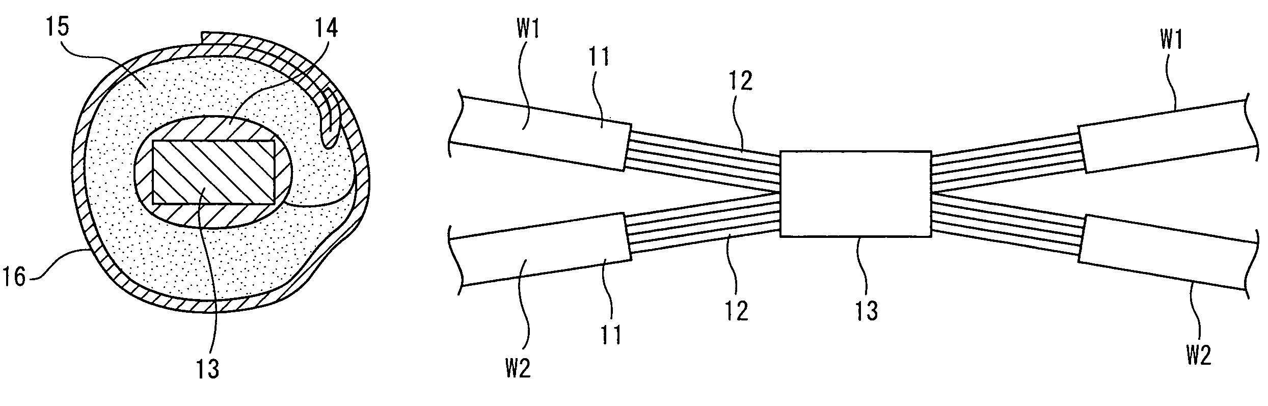
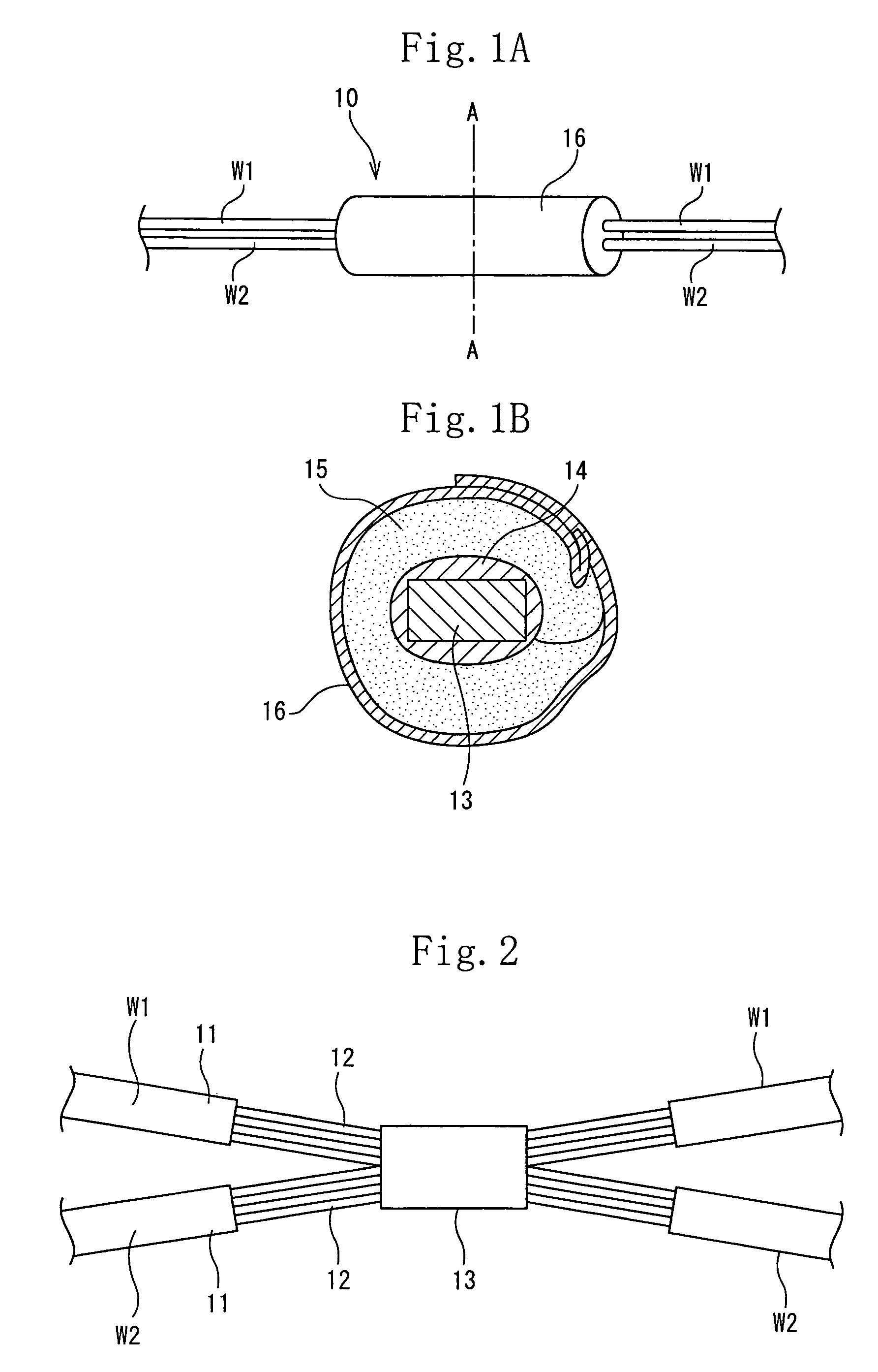
[0062]FIGS. 1 through 5 show the present invention. Cores 12 exposed by peeling insulating covers 11 of electric wires w1, w2 at a central position of each of the electric wires w1, w2 are welded by ultrasonic wave to form a connecting part 13. The connecting part 13, the exposed cores 12 disposed at both sides of the connecting part 13, and a tip portion of each of the insulating covers 11 continuous with the cores 12 respectively are embedded in silicone 14. A foamed sheet 15 and an adhesive tape 16 are wrapped around the silicone 14 to surround the silicone 14 completely to form a waterproof structure 10.

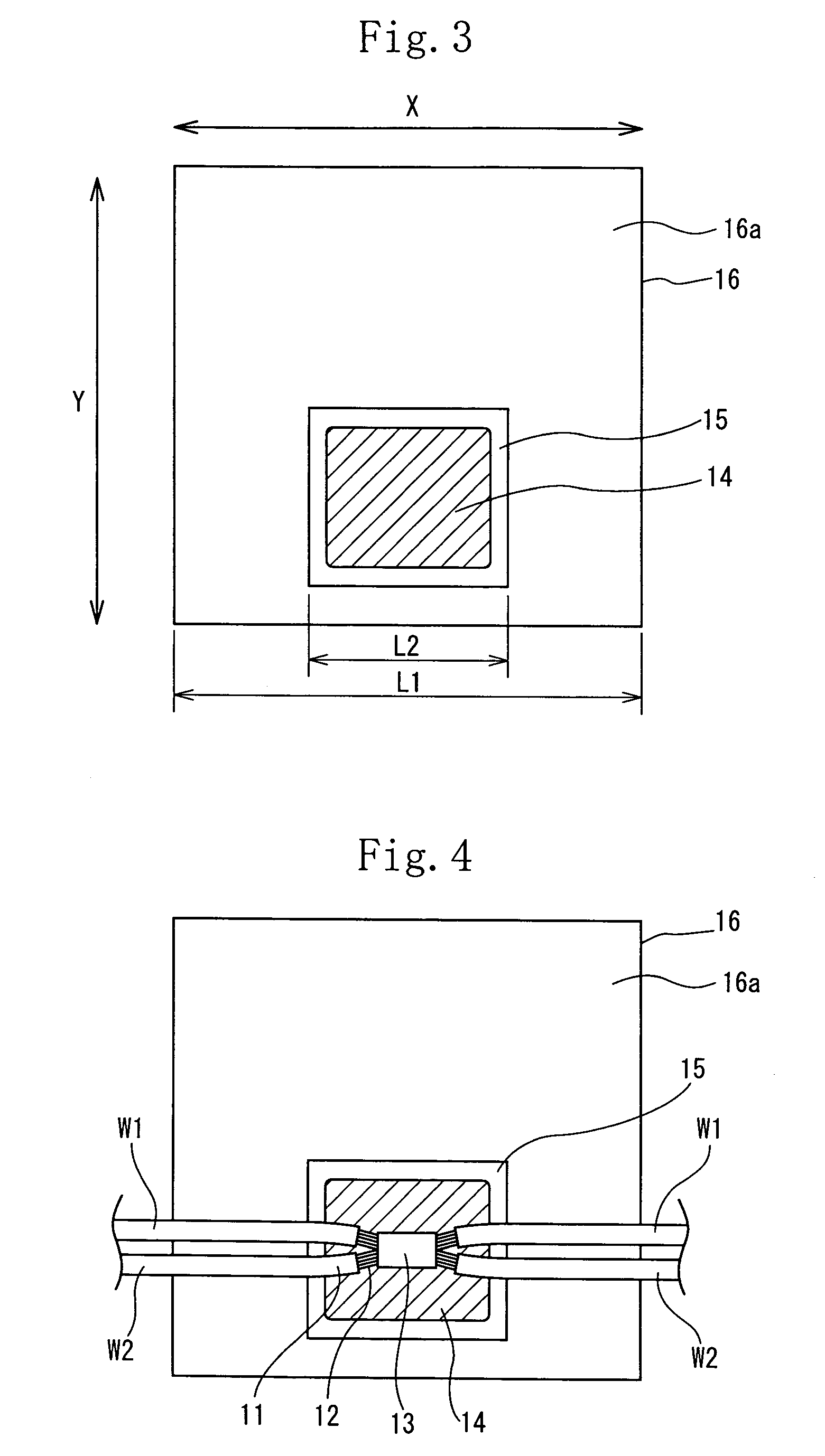
[0063]As shown in FIG. 3, the foamed sheet 15 and the adhesive tape 16 are both rectangular before they are wrapped around the electric wires w1, w2. A length L1 of the adhesive tape 16 in an axial direction X of the connecting part 13 is set to 65 mm. A length L2 of the foamed sheet 15 in the axial direction X of the connecting part 13 is set to not more than 80% of the length L...

second embodiment

[0082]FIGS. 10 and 11 show a second modification of the second embodiment in which a quadrangular concavity 15a is formed at one side of the foamed sheet 15, and a quadrangular convexity 15b is formed at the opposed other side thereof. When the foamed sheet 15 and the adhesive tape 16 are folded at a position where the electric wires w1, w2 are disposed, a state shown in FIG. 11 is obtained. The foamed sheet 15 is not overlapped on the broken line 1 at which the foamed sheet 15 is folded by the tape-wrapping machine. Therefore in the second modification, it is possible to obtain an effect similar to that of the first modification.

[0083]FIGS. 12 and 13 show a third embodiment of the present invention. In the third embodiment, the adhesive tape is not used, but a sheath 20, made of resin, in which ends of a pair of semicircular annular members 20a are coupled to each other with a thin hinge portion 20b is used. At the other end of the two semicircular annular members 20a, a locking po...


PUM


Abstract

A waterproof structure and a waterproof method for a wire connecting part, wherein the insulating coatings of a plurality of wires are peeled, and exposed cores are connected to each other by welding, soldering, or through a crimp style terminal. A foam sheet impregnated with a silicone and an adhesive tape are wrapped around the connecting part, and the silicone is filled in clearances between the connected cores.

Description

TECHNICAL FIELD[0001]The present invention relates to a waterproof structure of an electric wire connecting part and a waterproof method. More particularly the present invention is intended to waterproof the electric wire connecting part by filling silicone in the electric wire connecting part at which cores of electric wires exposed by peeling insulating covers thereof are connected to each other.BACKGROUND ART[0002]Heretofore, in connecting a plurality electric wires to each other in a wire harness to be mounted in a car, an insulating cover of each electric wire is peeled to expose each core thereof, and exposed portions of the cores are connected to each other by welding, soldering or with a pressure terminal to form a connecting part. When the connecting part is covered with water, the cores and the pressure terminal are corroded. Thus in the wire harness disposed at an engine room side which is a region into which water penetrates, a waterproof structure is formed at the conne...

Claims


Application Information

Patent Timeline
Patent Type & Authority Patents(United States)
IPC IPC(8): H01R4/00H01R4/18H01R4/70H01R13/52H01R43/00H02G1/14H02G15/08H02G15/18
CPCH01R13/5213H02G15/18H02G1/14H01R4/186H01R13/5216
Inventor OTSUKI, HIROYUKIHISAKI, YOSHIHIROITOU, TAKEHARU
Owner SUMITOMO WIRING SYST LTD
Why Eureka
Try Eureka