Liquid crystal display device

a liquid crystal display and color technology, applied in non-linear optics, instruments, optics, etc., to achieve the effect of high contrast ratio, reduced light irradiation amount during a single light irradiation operation, and increased total time of light irradiation operations

Active Publication Date: 2009-08-11
JAPAN DISPLAY INC +1
View PDF10 Cites 5 Cited by
  • Summary
  • Abstract
  • Description
  • Claims
  • Application Information

AI Technical Summary

Benefits of technology

[0015]The present invention is featured by that in a phase plate built-in type IPS liquid crystal display device, a reflectance of a light display can be improved, and, at the same time, a reflectance of a dark display can be improved.
[0019]When the phase difference layer formed in the above-described manner is put for a long time under high temperature condition, lowering of a retardation value thereof occurs. This mechanism may be explained based upon, for instance, a thermal relaxation mechanism. That is, since the orientation status in the liquid crystal phase is not always under the most stable status in view of the thermodynamic idea when the orientation film is solidified, a thermal relaxation is produced by a heating process which is performed after the phase difference layer has been formed, so that the orientation status is disturbed. As a result, the retardation value is lowered. At this time, if a couple forming rate caused by the optical polymerization reaction is high, then the orientation status in the liquid crystal phase is strongly held, so that the thermal relaxation can hardly occur. However, if a light irradiation amount is small and a couple forming rate is low, then the orientation status may be readily deformed, and lowering of the retardation value caused by the thermal relaxation may readily occur.
[0021]In order that the light irradiation amount only for the blue pixel is decreased when the phase difference layer is formed, either a half tone mask or a gray scale mask may be employed when the light is irradiated. The half tone mask reduces an averaged light irradiation amount based upon very small drawing smaller than, or equal to a resolution limit. As the very small drawing smaller than, or equal to the resolution limit, there are a very fine stripe-shaped pattern and the like. The gray scale mask reduces the light irradiation amount by a semi-transparent portion.
[0023]As previously described, in accordance with the present invention, since the half tone mask and the gray scale mask are employed, the light irradiation amount during a single light irradiating operation can be reduced only for the phase difference layer corresponding to the blue pixel. As a consequence, while the process steps are not made cumbersome (for example, total time of light irradiation operations is increased, and total number of forming operations for phase difference layer is increased), the retardation value only for the phase difference layer corresponding to the blue pixel can be decreased. As a result, in the transflective IPS type liquid crystal display device, the transmission display of the high contrast ratio can be realized with the wide view angle, and furthermore, the reflection display of the high contrast ratio can be realized in the high reflectance.
[0024]Also, if the liquid crystal display device of the present invention is employed as an interface of a mobile appliance such as a cellular phone, then high image quality displays can be obtained under various sorts of environments which include darkrooms up to outdoor under direct rays of the sun. In near future, there is such a trend that image data having large storage capacities are handled in conjunction with improvements in communication speeds. Also, in such a case, the liquid crystal display device of the present invention can precisely reproduce the contents of high image qualities under all of various environments.

Problems solved by technology

However, in this alternative case, manufacturing steps become cumbersome, and moreover, a total number of layers formed on a first substrate is increased, so that an optical transmittance is lowered, resulting in an undesirable effect.

Method used


Image

  • Liquid crystal display device
  • Liquid crystal display device
  • Liquid crystal display device

Examples


embodiment 1

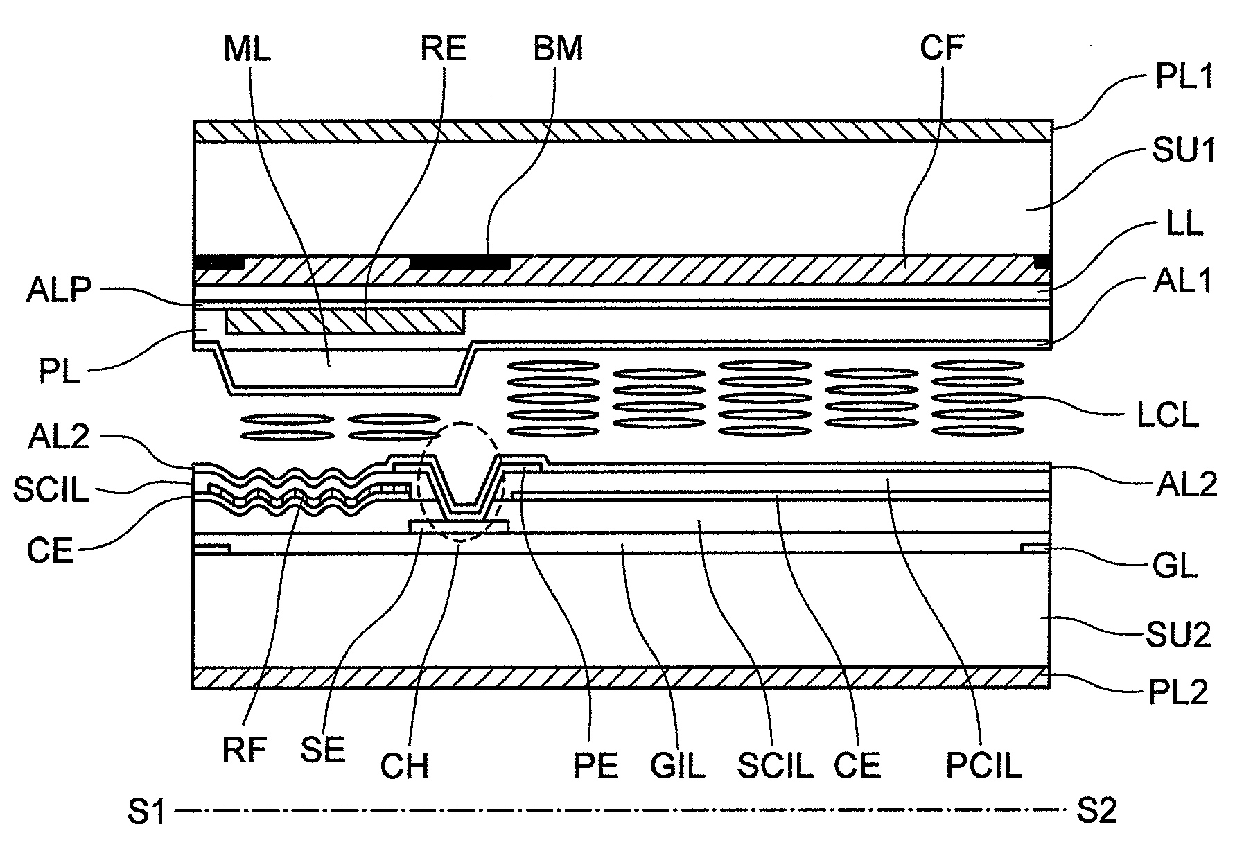
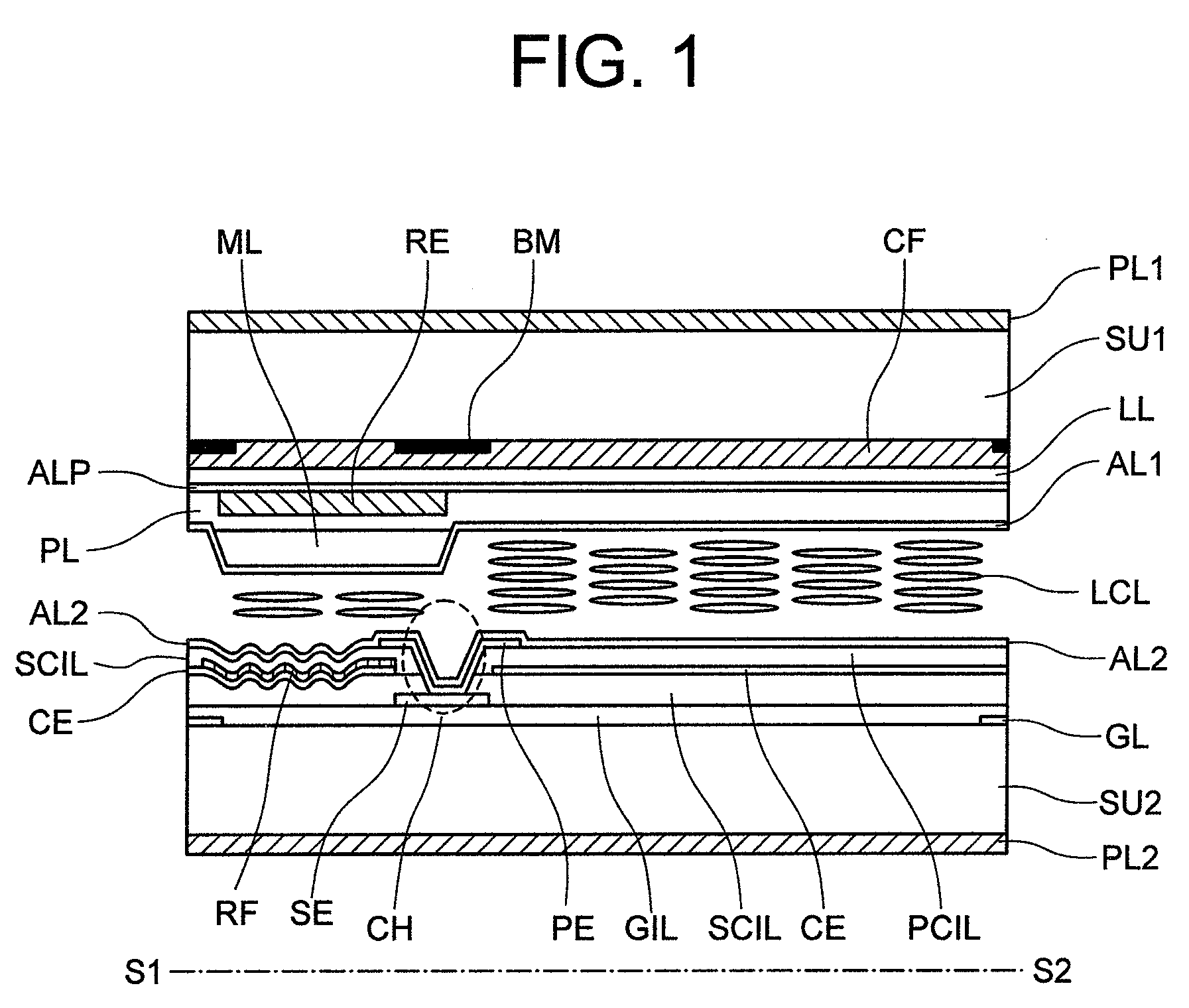
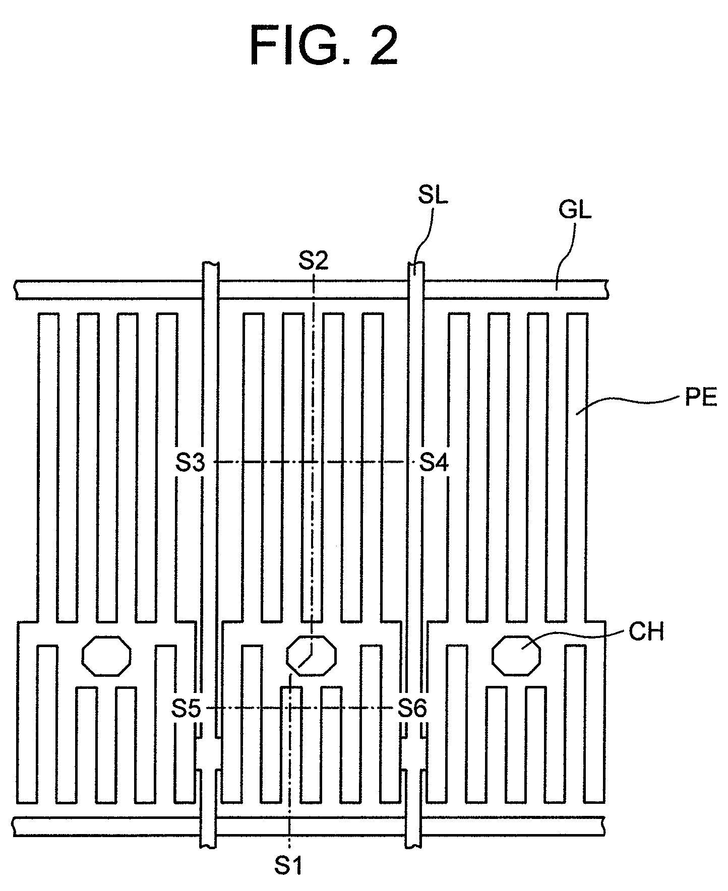
[0049]Sectional planes of 1 pixel of a liquid crystal display device according to the present invention are schematically indicated in FIG. 1, FIG. 3, and FIG. 4. It should be understood that cutting lines in the respective cutting sectional planes are represented in FIG. 2.

[0050]A liquid crystal display panel is constructed by employing a first substrate “SU1” and a second substrate “SU2”, while the first substrate “SU1” and the second substrate “SU2” sandwich a liquid crystal layer “LCL.” The first substrate SU1 and the second substrate SU2 are equipped with orientation films “AL1” and “AL2” on planes located in the vicinity of the liquid crystal layer LCL, while these orientation films “AL1” and “AL2” are employed so as to stabilize an orientation status of the liquid crystal layer LCL. Also, a means for applying a voltage to the liquid crystal layer LCL is provided on a plane located in the vicinity of the liquid crystal layer LCL of the second substrate SU2. Also, as represente...

embodiment 2

[0103]If the retardation value of the phase difference layer is increased larger than 340 nm and the retardation value of the reflection portion liquid crystal layer is also increased in connection thereto in such a manner that this retardation value is kept as approximately ½ with respect to the retardation value of the phase difference layer, then a higher reflectance of a light display can be obtained. In other words, the thickness of the reflection portion liquid crystal layer can be increased, so that the influence caused by the orientation control force is reduced, and thus, the orientation of the liquid crystal layer can be readily changed when a voltage is applied. Also, since the retardation value of the liquid crystal layer is increased, a change in an optical characteristic when the orientation is changed is increased. However, at this time, a dark display reflection spectrum in the short wavelength range is further increased, so that a reflection contrast ratio is largel...

embodiment 3

[0106]In the above-described embodiment 1, while the slow axis azimuth angle θRE=±67.5 degrees, the same dark display reflectance is given at any angles, but the light display reflectances are different from each other. With respect to each of the angles, if a relationship among liquid crystal orientation azimuth, slow axis azimuth of a phase difference layer, and a slit direction is illustrated, then 4 different sorts of these relationships are given in FIG. 14A to FIG. 14D.

[0107]FIG. 14A to FIG. 14D are plane views of the mutual relationships as observed along a normal direction of a substrate. FIG. 14A and FIG. 14B show such a mutual relationship in the case that the liquid crystal direction “LCAL” is 15 degrees along the counter clockwise direction with respect to the slit direction of the pixel electrode “PE”; and FIG. 14C and FIG. 14D show such a mutual relationship in the case that the liquid crystal direction “LCAL” is 15 degrees along the clockwise direction with respect to...


PUM

PropertyMeasurementUnit
angleaaaaaaaaaa
thicknessaaaaaaaaaa
wavelengthaaaaaaaaaa

Abstract

In a transflective type IPS type liquid crystal display device in which a phase difference layer has been built in a reflection display portion, a retardation value of the phase difference layer corresponding to a short wavelength color filter is different from a retardation value of the phase difference layer corresponding to a long wavelength color filter; while a blue display pixel is set to the short wavelength color filter and both red and green pixels are set to the long wavelength filter, the retardation value of the phase difference layer corresponding to the former-mentioned short wavelength color filter is made smaller than the retardation value of the phase difference layer corresponding to the latter-mentioned long wavelength color filter.

Description

CLAIM OF PRIORITY[0001]The present application claims priority from Japanese application JP-2006-300357 filed on Nov. 6, 2007 the content of which is hereby incorporated by reference into this application.BACKGROUND OF THE INVENTION[0002]The present invention generally relates to a transflective type IPS type color liquid crystal display device. More specifically, the present invention is directed to a phase difference layer of a reflection display portion of the color liquid crystal display device.[0003]Portable type information appliances which are typically known as cellular phones will be firmly progressed with having multiple functions and high performance also in near future, while storage capacities of storage devices thereof are increased and communication speeds thereof are increased. Also, with respect to display devices functioning as interfaces for these portable type information appliances, these display devices are necessarily required to be drivable in response to lar...

Claims


Application Information

Patent Timeline
Patent Type & Authority Patents(United States)
IPC IPC(8): G02F1/1335
CPCG02F1/13363G02F1/133555G02F1/134363G02F2001/133565G02F2413/14G02F2413/09G02F2413/11G02F2413/13G02F2001/133633G02F1/133634G02F1/133565G02F1/133631G02F1/133633
Inventor ITOU, OSAMUHIROTA, SHOICHIADACHI, MASAYAOKA, SHINICHIRO
Owner JAPAN DISPLAY INC
Why Eureka
Try Eureka