Multi-function high-speed network interface

a network interface and multi-functional technology, applied in the field of high-speed network interfaces, can solve problems such as errors in the data recovery process

Inactive Publication Date: 2009-08-11
CISCO TECH INC
View PDF25 Cites 286 Cited by
  • Summary
  • Abstract
  • Description
  • Claims
  • Application Information

AI Technical Summary

Benefits of technology

[0012]The present invention comprises a method for encoding and decoding data referred to as GX packets, a transmit processor, and a receive processor. The transmit processor includes a transmit buffer / controller dividing the data into a plurality of transmit data lanes, a plurality of transmit encoders, each encoder accepting information from a unique transmit data lane and producing an output stream of clock-encoded data, and a plurality of transmit serializers, each accepting a unique stream of transmit encoded data, and serially encoding it for transmission. A variable-speed transmit clock circuit affords clocking of the elements of the transmit processor. The transmit encoders add clock recovery information to the data stream, optionally using the 8B / 10B encoding method, and also insert START, END, IDLE_EVEN, IDLE_ODD, IDLE_EVEN_BUSY, and IDLE_ODD_BUSY information as instructed by the input buffer / controller. The receive processor comprises a plurality of receive deserializers, each receiving a serial stream of encoded data, and producing a stream of parallel encoded data. These encoded parallel streams are passed on to a plurality of receive decoders, each of which decodes a stream of encoded data into a stream of byte information, as well as decoding control information such as START, END, IDLE_EVEN, IDLE_ODD, IDLE_EVEN_BUSY, and IDLE_ODD_BUSY. The receive processor / controller accepts these streams of data and control signals, organizes the recovered byte streams into recovered packets, and also reports errors associated with the data recovery process. A recovered receive clock for each data lane is used to clock synchronized data into the elasticity buffer of the receive processor.

Problems solved by technology

The receive processor / controller accepts these streams of data and control signals, organizes the recovered byte streams into recovered packets, and also reports errors associated with the data recovery process.

Method used


Image

  • Multi-function high-speed network interface
  • Multi-function high-speed network interface
  • Multi-function high-speed network interface

Examples


Embodiment Construction

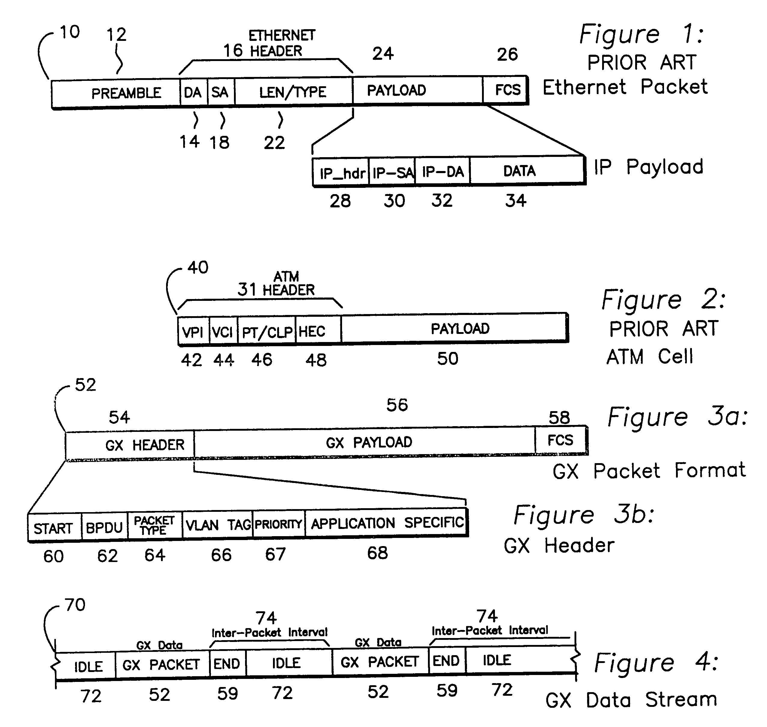
[0036]FIG. 1 shows a prior art layer 2 Ethernet Packet 10, comprising a preamble 12, a header 16 comprising a MAC Destination Address 14, a MAC Source Address 18, and length / type information 22. Payload 24 is followed by the Frame Check Sequence 26 which is a Cyclical Redundancy Check (CRC) polynomial applied over the entire Ethernet header 16 and payload 24. For a generic layer 2 Ethernet packet, payload 24 contains the data. In the case of a layer 3 protocol such as IP, payload 24 is arranged to further comprise an IP header 28, an IP source address 30, and an IP destination address 32, followed by the IP data 34. Other layer 3 protocols such as Appletalk, IPX, and the like have alternate arrangements for payload 24, but in general carry a layer-related source and destination address observed by the particular protocol. Other attributes of Ethernet packet 10 include variable length payload 24, which may vary from 46 bytes to 1500 bytes, as defined in the MAC layer specification IE...


PUM


Abstract

A high speed communications interface divides data into a plurality of lanes, each lane encoded with clocking information, serialized, and sent to an interface. During cycles when there is no available data to send, IDLE_EVEN and IDLE_ODD cells are sent on alternating cycles. Data is transmitted by sending a header which spans all lanes and includes a START symbol. The final data transaction includes a Frame Check Sequence (FCS) which operates over the entire header and data. The packet is terminated by an END symbol, which is sent after the final data, and the remainder of the lanes are padded with IDLE_EVEN, IDLE_ODD, IDLE_EVEN_BUSY, or IDLE_ODD_BUSY cycles. The interface has a variable clock rate.

Description

[0001]This is a continuation of U.S. patent Ser. No. 09 / 339,963, now U.S. Pat. No. 6,956,852, filed Jun. 25, 1999.FIELD OF THE INVENTION[0002]The current data communication invention is directed to a high speed network interface that is capable of the transmission and reception of multiple types of variable length data packets. In addition, the invention includes a media access control mechanism. Data packets can be sent over a variety of physical media, including single mode fiber, multi-mode fiber, and parallel fibers.BACKGROUND OF THE INVENTION[0003]In data communications networks, a large number of methods are used to encapsulate communication data packets such as OSI (Open Systems Interconnect) layer 3 TCP / IP packets for the purpose of transmission over local or layer 2 networks and over specific point to point layer 1 physical links. Examples of OSI layer 2 network encapsulation and transmission and access control methods include 10 Mb Ethernet, 100 Mb Ethernet, gigabit Ethern...

Claims


Application Information

Patent Timeline
Patent Type & Authority Patents(United States)
IPC IPC(8): H04J3/02H04L12/56H04L12/66H04Q11/00H04L12/00H04L12/413H04L12/46
CPCH04L12/4641H04L12/4633
Inventor BECHTOLSHEIM, ANDREAS V.FRAZIER, HOWARD M.EDSALL, THOMAS J.
Owner CISCO TECH INC
Why Eureka
Try Eureka