Power control apparatus and method of using a power control apparatus in an image forming device

a power control apparatus and image forming technology, applied in the field of electrographic image forming devices, can solve the problems of user distraction, user inability to replace the transfer belt, and generally cannot remove the jammed paper, so as to reduce manufacturing costs, simplify the configuration, and reduce the effect of layou

Active Publication Date: 2009-08-11
HEWLETT PACKARD DEV CO LP
View PDF6 Cites 9 Cited by
  • Summary
  • Abstract
  • Description
  • Claims
  • Application Information

AI Technical Summary

Benefits of technology

[0015]Aspects of the present invention provide a power control apparatus and method of using a power control apparatus in an image forming device, which has reduced manufacturing costs and an efficient layout, by simplifying a configuration in which a connection state of a paper transfer belt (PTB) unit is sensed, through the implementation of a simple method using a feedback signal of power supplied to the PTB unit and power supplied to a laser scanning unit (LSU), wherein the power control apparatus is controlled according to the sensed connection state of the PTB unit.
[0017]Aspects of the present invention also provide a power control apparatus and method of using a power control apparatus in an image forming device to control power supplied to various kinds of sensors and memory units included in a PTB unit in a stable fashion, according to the opening and closing of an outer cover of an image forming device, in order to prevent the sensors and memory units included in the PTB unit from operating incorrectly and / or operating out of order due to a mistake of a user, when the image forming device abnormally operates due to the opening and closing of the outer cover.
[0018]Aspects of the present invention also provide a power control apparatus and a method of using a power control apparatus in an image forming device, wherein the apparatus and method are competitively priced and efficiently structured by simplifying a configuration to control various kinds of sensors and memory units included in a PTB unit.

Problems solved by technology

In an image forming device, when a paper jam, in which printing paper fed by a paper transfer belt (PTB) unit is jammed in a transfer belt, occurs, a user generally cannot remove the jammed paper until after opening an outer cover of the image forming device.
Similarly, when the transfer belt, which is a replaceable part, must be changed, a user cannot replace the transfer belt until after separating the PTB unit from the image forming device.
In particular, if a laser beam is irradiated on the eyes of the user, various problems may occur, such as the laser beam distracting the user.
Since a plurality of micro-switches must be installed, the space required to install the plurality of micro-switches is large, the manufacturing costs of the conventional power control apparatus are high, and the mechanical embodiment is complicated.
Furthermore, the conventional control apparatus illustrated in FIG. 2B also has drawbacks.
For an image forming device using a single path method, since laser beams to which yellow, magenta, cyan, and black images are exposed must all be blocked, the conventional power control apparatus illustrated in FIG. 2B must have at least four LSU shutters 160, resulting in a spatial problem and high manufacturing costs.

Method used


Image

  • Power control apparatus and method of using a power control apparatus in an image forming device
  • Power control apparatus and method of using a power control apparatus in an image forming device
  • Power control apparatus and method of using a power control apparatus in an image forming device

Examples


Embodiment Construction

[0036]Reference will now be made in detail to the present embodiments of the present invention, examples of which are illustrated in the accompanying drawings, wherein like reference numerals refer to the like elements throughout. The embodiments are described below in order to explain the present invention by referring to the figures.

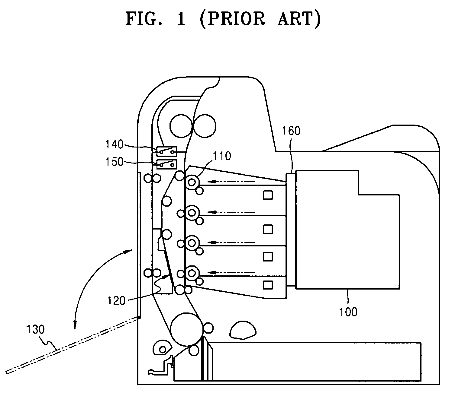
[0037]FIG. 3 is a side view of on image forming device which has a power control apparatus according to an embodiment of the present invention. The image forming device in FIG. 3 includes a light scanning unit (LSU) 400, a photosensitive medium 310, a paper transfer belt (PTB) unit 420, an outer cover 330, a cover switch 440, and a connection unit 490.

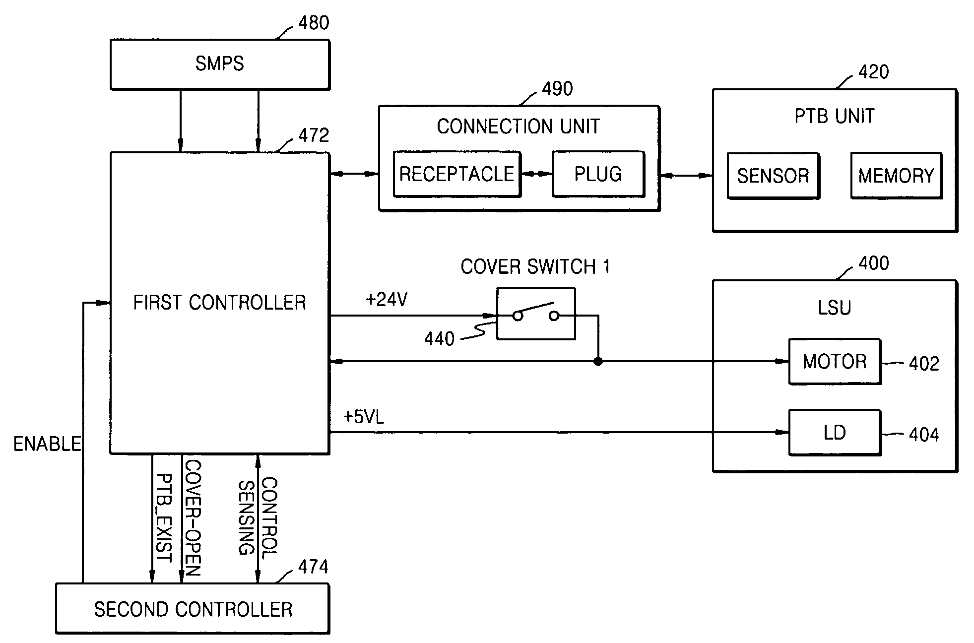
[0038]FIG. 4 is a block diagram of a power control apparatus according to an embodiment of the present invention. Referring to FIG. 4, the power control apparatus includes the laser scanning unit (LSU) 400, the paper transfer belt (PTB) unit 420, the connection unit 490, a first controller 472, a second c...


PUM


Abstract

A method and apparatus to control power supplied to a paper transfer belt (PTB) unit and a laser scanning unit (LSU) included in an image forming device includes the PTB unit to transfer a developed latent image onto a printing medium, the LSU to scan light onto a photosensitive medium, a first controller to control power supplied to the PTB unit and the LSU, and a connection unit to connect the PTB unit to the first controller, wherein the first controller controls the power supplied to the LSU according to a connection state of the connection unit.

Description

CROSS-REFERENCE TO RELATED APPLICATION[0001]This application claims the benefit of Korean Application No. 2006-68090, filed Jul. 20, 2006, in the Korean Intellectual Property Office, the disclosure of which is incorporated herein by reference.BACKGROUND OF THE INVENTION[0002]1. Field of the Invention[0003]Aspects of the present invention relate to an electrographic image forming device, and more particularly, to a method and apparatus to control power supplied to a paper transfer belt (PTB) unit and a laser scanning unit (LSU) according to whether a cover of an image forming device is open or closed and whether the PTB unit is installed within the image forming device.[0004]2. Description of the Related Art[0005]In an image forming device, when a paper jam, in which printing paper fed by a paper transfer belt (PTB) unit is jammed in a transfer belt, occurs, a user generally cannot remove the jammed paper until after opening an outer cover of the image forming device. Similarly, when...

Claims


Application Information

Patent Timeline
Patent Type & Authority Patents(United States)
IPC IPC(8): G03G15/00B41J2/385G03G13/04
CPCG03G15/5004G03G15/80G03G21/1652G03G2221/166G03G2221/1687G03G2215/0119G03G15/04
Inventor EOM, YOON-SEOP
Owner HEWLETT PACKARD DEV CO LP
Why Eureka
Try Eureka