

Systems and methods for whole-house dehumidification based on dew point measurements
- Summary
- Abstract
- Description
- Claims
- Application Information
AI Technical Summary
Benefits of technology
Problems solved by technology
Method used
Image

Examples
Embodiment Construction
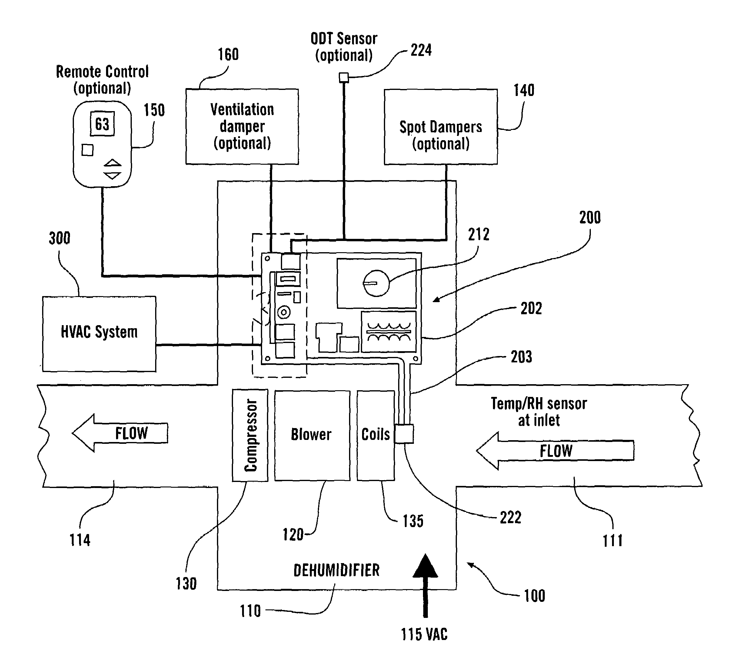
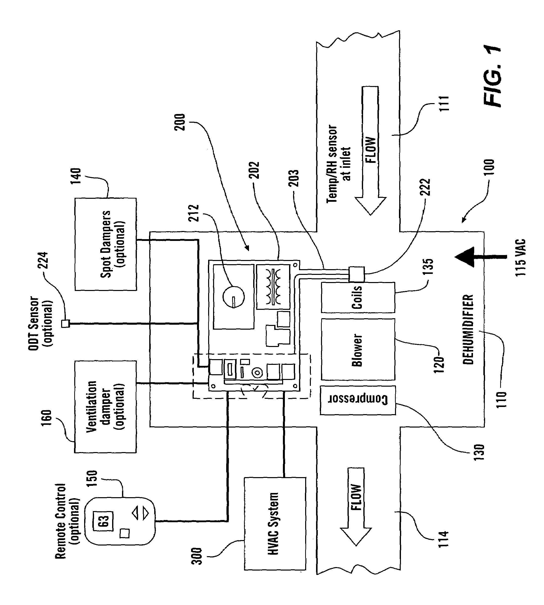
[0010]The '715 patent discloses dehumidification systems that use the HVAC blower to provide the operative energy to force the air to be dehumidified through the dehumidifier unit itself and through the duct work between the dehumidifier and the HVAC unit. The air to be dehumidified is withdrawn from the HVAC system downstream of the air conditioning unit and the dehumidified air is returned to the HVAC system upstream of the air conditioning unit. The inventors have determined that, in the '715 system, re-evaporation of water off of the air conditioning coils into the previously dehumidified air could lower or even negate the effect of the dehumidifier. That is, the coil will have moisture on it as it actively cools the air passing through the HVAC system and for a short time thereafter. If the air conditioning coil has moisture on it, the dry, warm dehumidified air returned to the HVAC system upstream of the air conditioning coil by the dehumidifier will pass over the air conditio...
PUM
| Property | Measurement | Unit |
|---|---|---|
| offset temperature | aaaaa | aaaaa |
| temperature | aaaaa | aaaaa |
| temperature | aaaaa | aaaaa |
Abstract
Description
Claims
Application Information