
Sensor for detecting particles in a gas stream and method for its manufacture

a technology of gas stream and sensor, which is applied in the direction of suspension, porous material analysis, material impedance, etc., can solve the problems of reducing the distance between the two electrodes and the durability of the operation, and achieves the effect of being particularly fast and inexpensive and being introduced very easily

Active Publication Date: 2009-08-18
ROBERT BOSCH GMBH
View PDF16 Cites 21 Cited by
  • Summary
  • Abstract
  • Description
  • Claims
  • Application Information

AI Technical Summary

Benefits of technology

The present invention relates to a sensor that can detect particles in a gas stream with high sensitivity and low response time. The sensor includes electrode devices that are separated from each other by an intermediate layer made of an electrically insulating material. The electrodes have free edges that are exposed to the gas stream and can be set apart from each other only by the thickness of the intermediate layer. The sensor is advantageously produced using foil technology, which simplifies production and reduces costs. The sensor can be designed with a small distance between the electrodes, which increases the sensitivity and reduces the effects of abrasion erosion on the surfaces of the electrodes. The sensor can also have several individual electrodes to increase the reliability of the sensor. The sensor can be heated to burn off particles deposited on its surface, and a temperature-sensing device can be included to monitor the heating process. The sensor can be produced using a foil technology method that simplifies production and reduces costs.

Problems solved by technology

A further reduction in distances between the two electrodes is difficult from the standpoint of production engineering in the case of the known sensors, and can lead to durability problems during operation.

Method used


Image

  • Sensor for detecting particles in a gas stream and method for its manufacture
  • Sensor for detecting particles in a gas stream and method for its manufacture
  • Sensor for detecting particles in a gas stream and method for its manufacture

Examples


Embodiment Construction

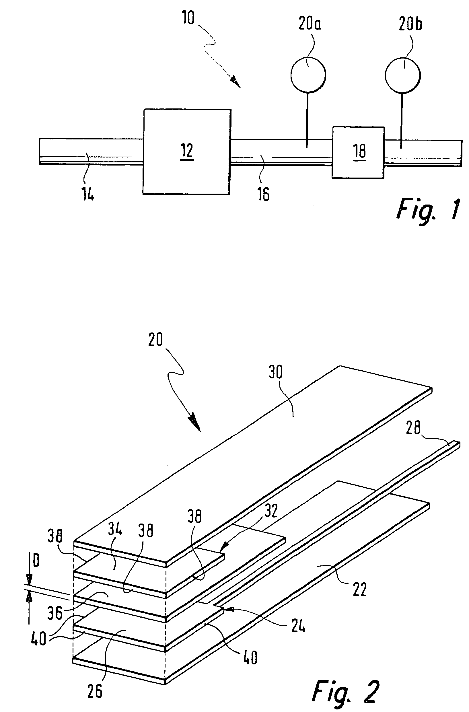
[0042]In FIG. 1, an internal combustion engine is designated generally by reference numeral 10. It includes an engine block 12, an intake manifold 14 and an exhaust pipe 16. Internal combustion engine 10 may be a diesel engine, for example. A soot-particle filter 18 is situated in its exhaust pipe 16.

[0043]Soot particles in the exhaust gas are stopped and collected by soot-particle filter 18. For reliable operation of internal combustion engine 10, it is necessary to detect a state in which soot-particle filter 18 has picked up so many soot particles that its permeability is restricted and, because of the filter loading, regeneration can no longer be ensured. If such a situation is recognized, soot-particle filter 18 must either be replaced or regenerated. To permit detection of such a situation, soot-particle sensors 20a and 20b are situated upstream and downstream of soot-particle filter 18 in exhaust pipe 16. They detect the loading of the exhaust gas with soot particles at the c...


PUM

PropertyMeasurementUnit
distancesaaaaaaaaaa
vertical distanceaaaaaaaaaa
thicknessaaaaaaaaaa

Abstract

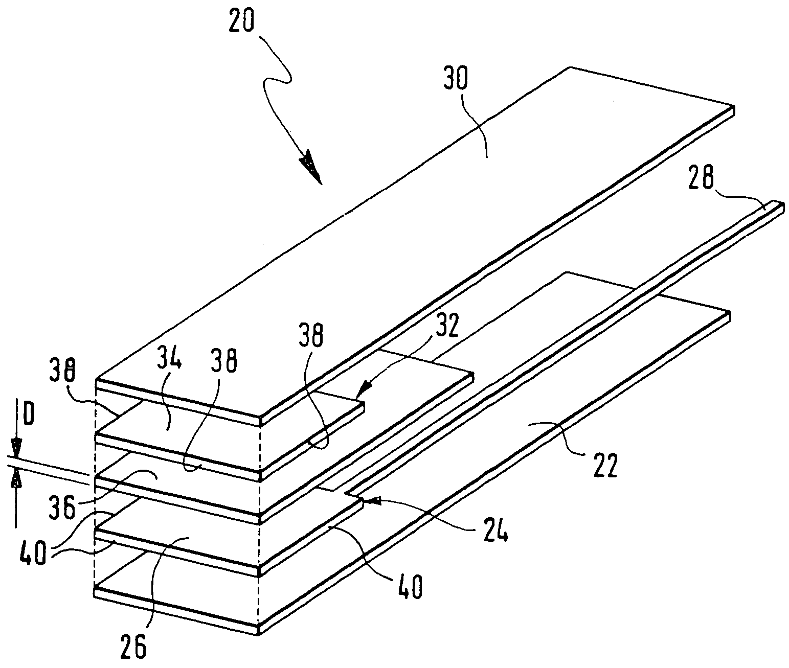
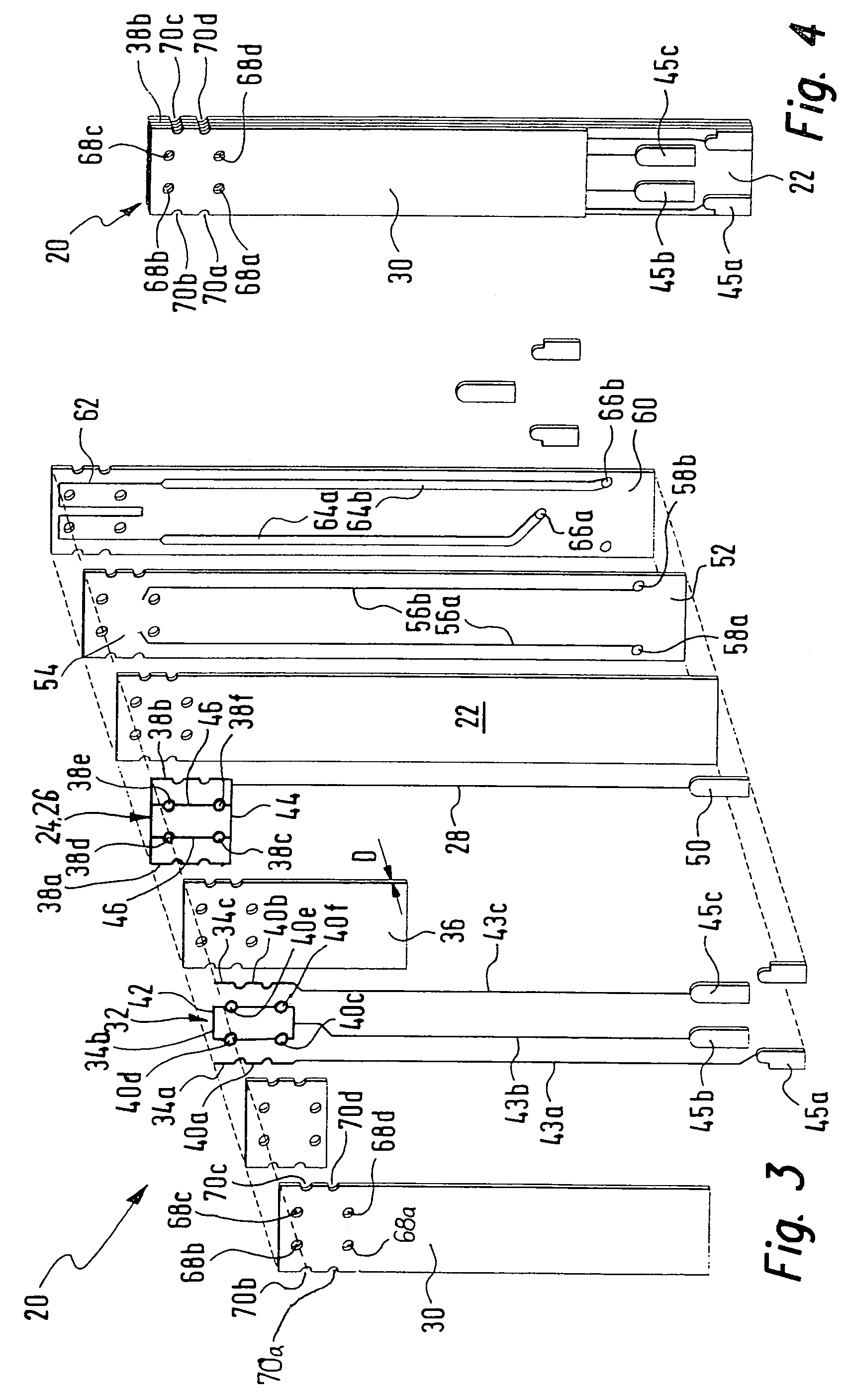
A soot particle sensor for an exhaust system of an internal combustion engine includes a first electrode device and a second electrode device. The electrode devices are situated at a distance from one another and are able to be exposed to the gas stream, at least in some areas. It is provided that the electrode devices are separated from each other by an intermediate layer made of an electrically insulating material, and the electrode devices have free edges that are set apart from each other by the thickness of the intermediate layer and are able to be exposed to the gas stream.

Description

FIELD OF THE INVENTION[0001]The present invention relates to a sensor for detecting particles in a gas stream, and relates particularly to a soot-particle sensor for an exhaust system of an internal combustion engine.BACKGROUND INFORMATION[0002]A sensor for detecting particles in an exhaust-gas stream is described in published German Patent Application DE 101 33 385. In the sensor described there, a collecting chamber is provided which can be coupled in fluid communication with an exhaust-gas stream of an internal combustion engine. A first electrode is situated on the upper side of the very flat collecting chamber, a second electrode on the lower side, thus opposite the first electrode. The collecting chamber between the two electrodes is hollow. When the known sensor is in operation, soot particles arrive in the collecting chamber and deposit in the hollow space between the two electrodes. The intervening space between the two electrodes is thereby electrically bridged, so that th...

Claims


Application Information

Patent Timeline
Patent Type & Authority Patents(United States)
IPC IPC(8): G01N27/02G01R3/00G01N15/06
CPCG01N15/0656Y10T29/49007
Inventor SCHNELL, FRANKSCHMIDT, RALFGLANZ, UWEROSCH, SABINEMARX, HELMUTSCHAENZLIN, KATHARINASCHITTENHELM, HENRIK
Owner ROBERT BOSCH GMBH
Learn More