Zone tillage tool and method

a technology of tillage and zone, applied in the field of farming practice, can solve the problems of degrading water quality, high economic and environmental cost, and expensive fertilization of large fields,

Active Publication Date: 2009-08-18
ENVIRONMENTAL TILLAGE SYST
View PDF35 Cites 94 Cited by
  • Summary
  • Abstract
  • Description
  • Claims
  • Application Information

AI Technical Summary

Problems solved by technology

While this full field tillage method of farming does produce large crops, it does so at a substantial economic and environmental cost.
It is expensive to fertilize large fields due to the need to purchase and spray large quantities of fertilizer.
Such fertilizer then becomes a pollutant, degrading water quality and promoting the growth of unhealthy vegetation, such as algae, in the waterway.
In addition, plowing an entire field under exposes the soil to the elements.
Wind and water act on the exposed soil and can blow or wash away large quantities of valuable and irreplaceable soil.
However, in the full field tillage method of farming under consideration, this crop residue has been plowed under and is no longer effective to prevent erosion.
Erosion of agricultural fields is a serious problem which could limit future food production by making the land less productive.
However, crop yields are generally not as high with no till farming as with full field tillage.
In addition, some farmers may have aesthetic objections to a no till field when compared to a plowed field.
Nonetheless, weed growth is significantly retarded since weed seeds in the untilled ground between adjacent zones remain undisturbed and since no fertilizer is applied to such untilled ground, thereby preventing or slowing the germination of the weed seeds and the growth of weeds.
Known zone tillage tools and methods have certain problems that limit wider adoption of zone tillage by farmers.
This is obviously inconvenient and time consuming.
When zone tillage has been tried on sloping ground, there has been a tendency for washouts to occur.

Method used


Image

  • Zone tillage tool and method
  • Zone tillage tool and method
  • Zone tillage tool and method

Examples


Embodiment Construction

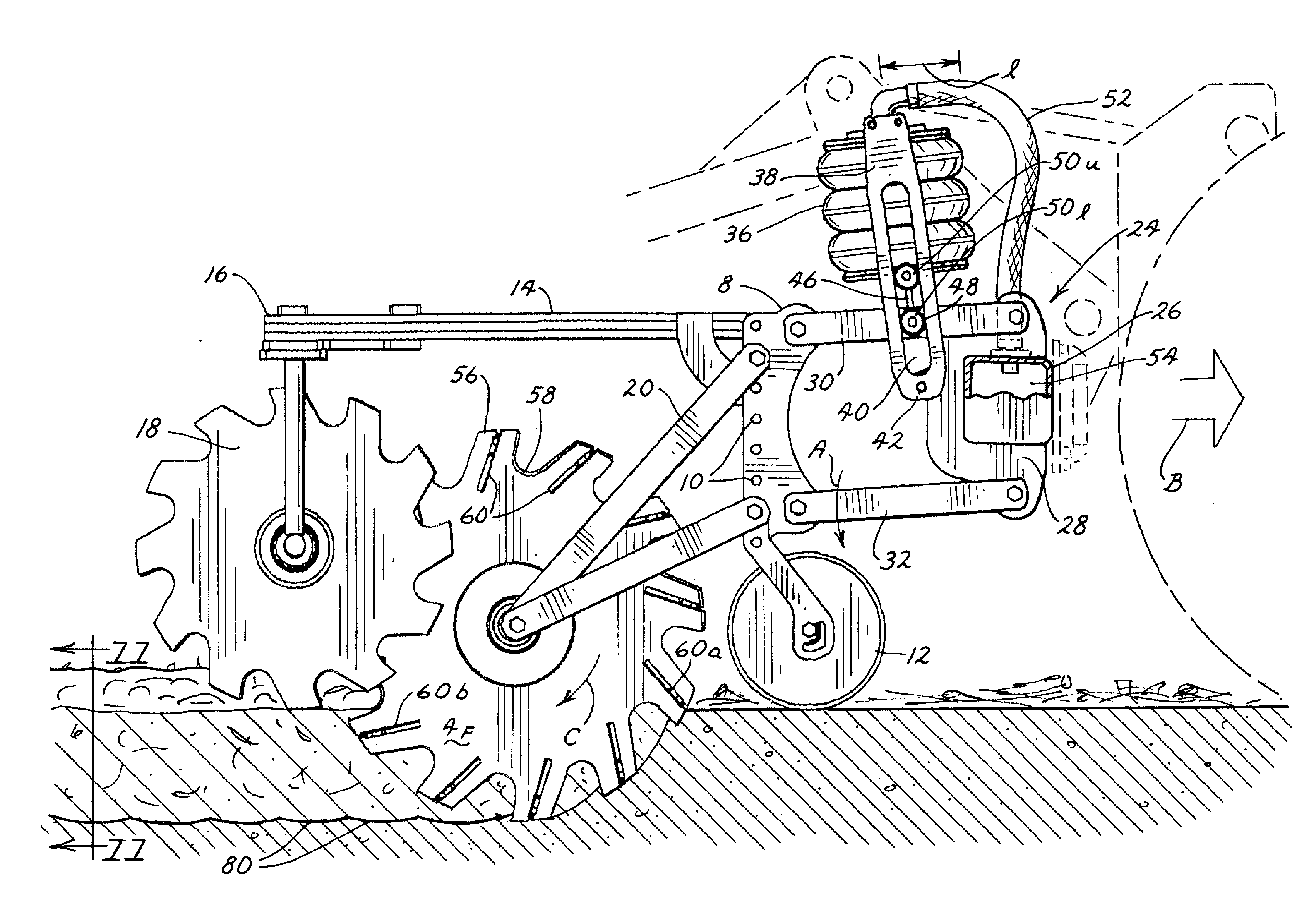
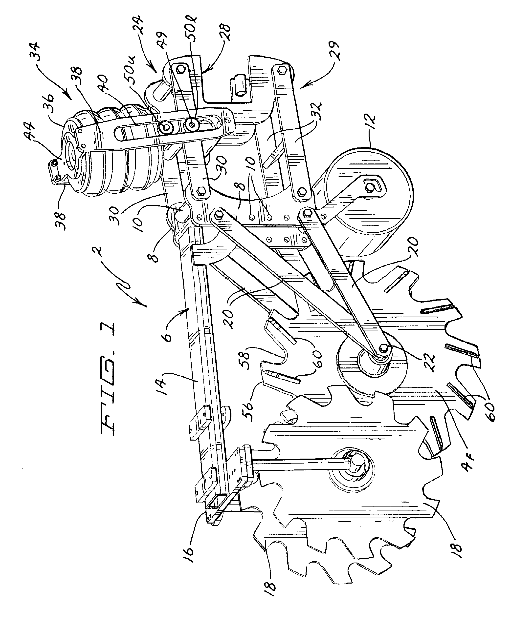
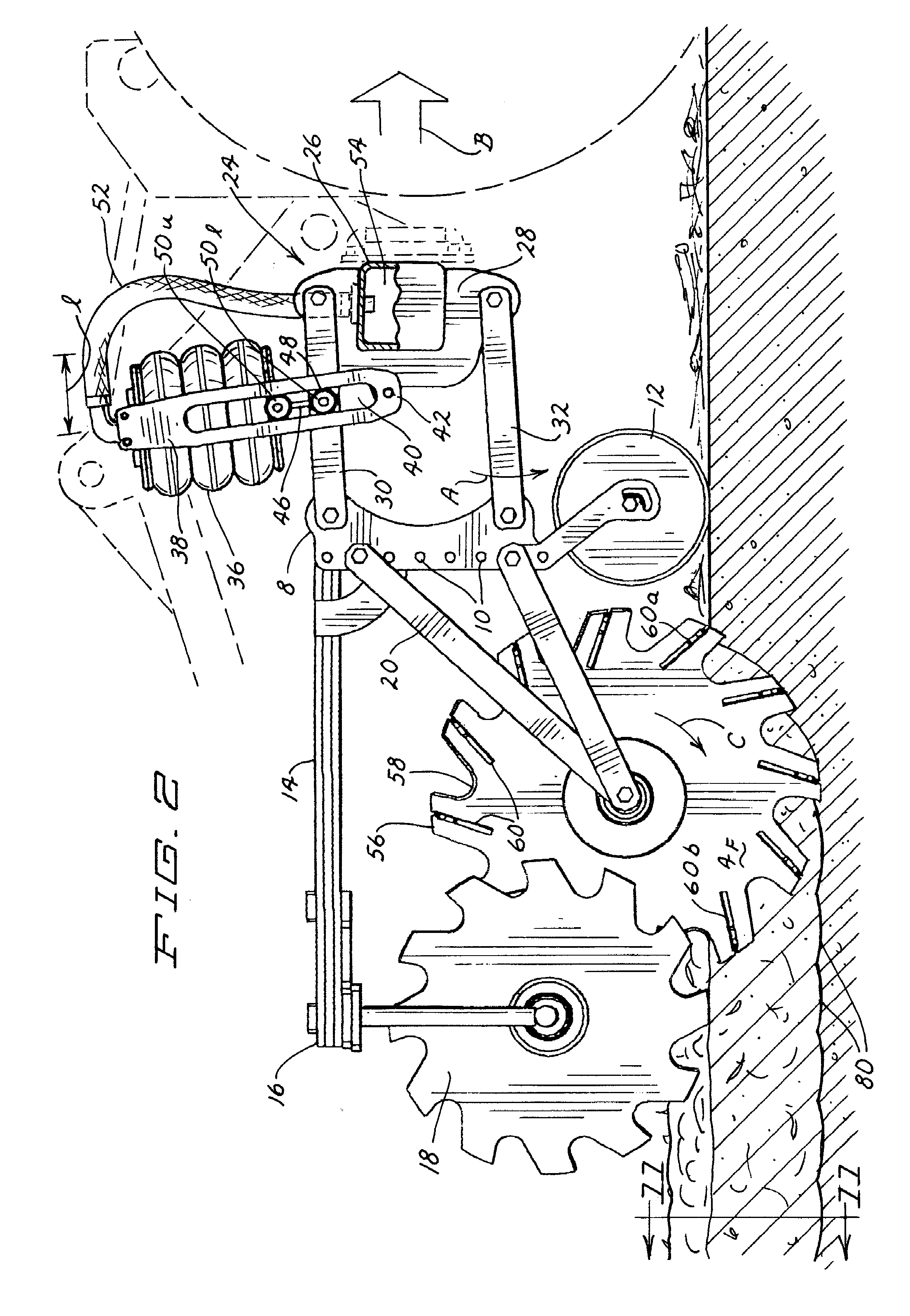
[0032]One embodiment of a zone tillage tool according to this invention is illustrated generally as 2 in FIG. 1. Tool 2 is shown equipped with a novel fall tillage coulter 4f for tillage in the fall after the usual harvest of a summer crop. FIG. 3 shows the same tool 2 equipped with a pair of spring tillage coulters 4s for tillage in the spring prior to planting. A new method of zone tillage will be described below in conjunction with the fall and spring tillage coulters 4f and 4s shown in FIGS. 1 and 3.

The Fall Tillage Configuration

The Tool Frame

[0033]Tool 2 has a tool frame 6 comprising a pair of spaced side plates 8 that are fixed together by one or more crosstubes 10. Side plates 8 each have an array of vertical mounting holes 10. A rotatable gauge wheel 12 may be installed in a selected one of different pairs of holes 10 to vary the height of tool frame 6 relative to the ground. When gauge wheel 12 is positioned in the lowest pair of holes 10, fall tillage coulter 4f is positio...


PUM


Abstract

A zone tillage tool comprises a tool frame connected by a parallel lift linkage to a tool bar. A fall tillage coulter or dual spring tillage coulters can be carried on the tool frame in advance of a pair of containment coulters. The fall tillage coulter tills soil in a zone that is approximately 7 to 9 inches deep while the spring tillage coulters till 2 to 3 inches deep. The fall tillage coulter includes a plurality of shovel bits located around the circumference thereof at a forward rake angle. The tip of each shovel bit has a generally vertical entry position into the ground due to the forward rake angle. As the fall tillage coulter rotates, the shovel bits rotate around and exit the soil in a generally horizontal position, thereby lifting and loosening the soil without compacting the soil through a series of rearwardly and upwardly directed soil scooping actions.

Description

CROSS REFERENCE TO RELATED APPLICATIONS[0001]This application claims the benefit of one or more previously filed copending provisional applications identified as follows: Application Ser. No. 60 / 614,009 filed Sep. 28, 2004.TECHNICAL FIELD[0002]This invention relates generally to a farming practice known as zone tillage. More particularly, this invention relates to a new method of zone tillage as well as to a new tillage tool developed for and used in this new method.BACKGROUND OF THE INVENTION[0003]During the twentieth century, most farmers began to heavily cultivate their land to increase crop yields. After the fall harvest, a farmer often plowed under the entire field from fence post to fence post. Fertilizer would often be applied over the entire field at the same time. Again, before the spring planting, the farmer would retill the field and apply more fertilizer to further prepare the soil for planting.[0004]While this full field tillage method of farming does produce large crop...

Claims


Application Information

Patent Timeline
Patent Type & Authority Patents(United States)
IPC IPC(8): A01B21/02
CPCA01B5/12A01C21/00A01C7/205A01C7/006Y02P60/20
Inventor BAUER, MARK A.
Owner ENVIRONMENTAL TILLAGE SYST
Why Eureka
Try Eureka