Gradient coil and magnetic resonance imaging apparatus using the same

a magnetic resonance imaging and coil technology, applied in the direction of instruments, magnetic measurements, measurement devices, etc., can solve the problems of difficult to obtain vibration of an internal structural member such as the coil, and difficulty in obtaining a clear image through magnetic resonance imaging, so as to reduce the generation of unnecessary magnetic fields

Active Publication Date: 2009-08-18
FUJIFILM HEALTHCARE CORP
View PDF12 Cites 4 Cited by
  • Summary
  • Abstract
  • Description
  • Claims
  • Application Information

AI Technical Summary

Benefits of technology

[0026]The present invention provides a gradient coil that is used for a magnetic resonance imaging apparatus and capable of reducing the generation

Problems solved by technology

This makes it difficult to obtain a clear image through magnetic resonance imaging.
If the gradient magnetic field leaks into those areas and interferes with the magnetomotive force source, a vibration of an internal structural member such as a coil vibration may occur.
This makes it difficult to obtain a clear image through magnetic resonance imaging.
Specifically, if a magnetic field is gen

Method used


Image

  • Gradient coil and magnetic resonance imaging apparatus using the same
  • Gradient coil and magnetic resonance imaging apparatus using the same
  • Gradient coil and magnetic resonance imaging apparatus using the same

Examples


first embodiment

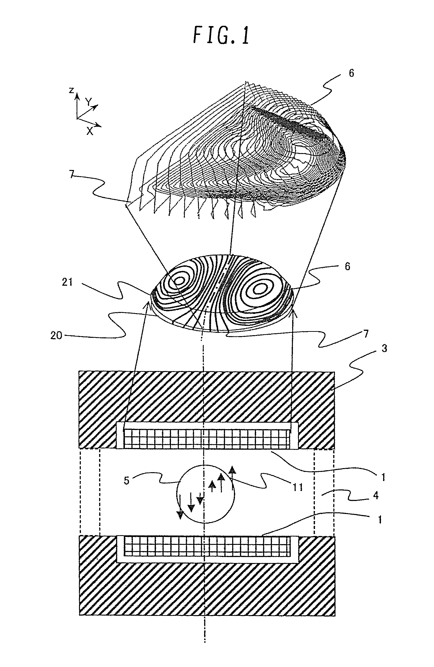
[0058]A first embodiment to which the gradient coil according to the present invention is applied will be described below with reference to FIGS. 1, 5, 6, 9, and 10. First, an MRI apparatus will be outlined. The MRI apparatus uses nuclear magnetic resonance to obtain an image representing physical and chemical properties of a subject to be inspected. The nuclear magnetic resonance is generated when the subject placed in a space (imaging area 5) in which a static magnetic field is substantially uniform is irradiated with a high frequency pulse. To be more specific, the MRI apparatus uses the property in which a nuclear magnetic resonance signal generated by hydrogen nuclei forming a biological body varies depending on the tissues. An electromagnetic wave emitted by a hydrogen nuclear spin in response to the nuclear magnetic resonance is measured. The measured electromagnetic wave is computed as a signal, thereby making it possible to obtain a cross sectional image of the subject.

[005...

second embodiment

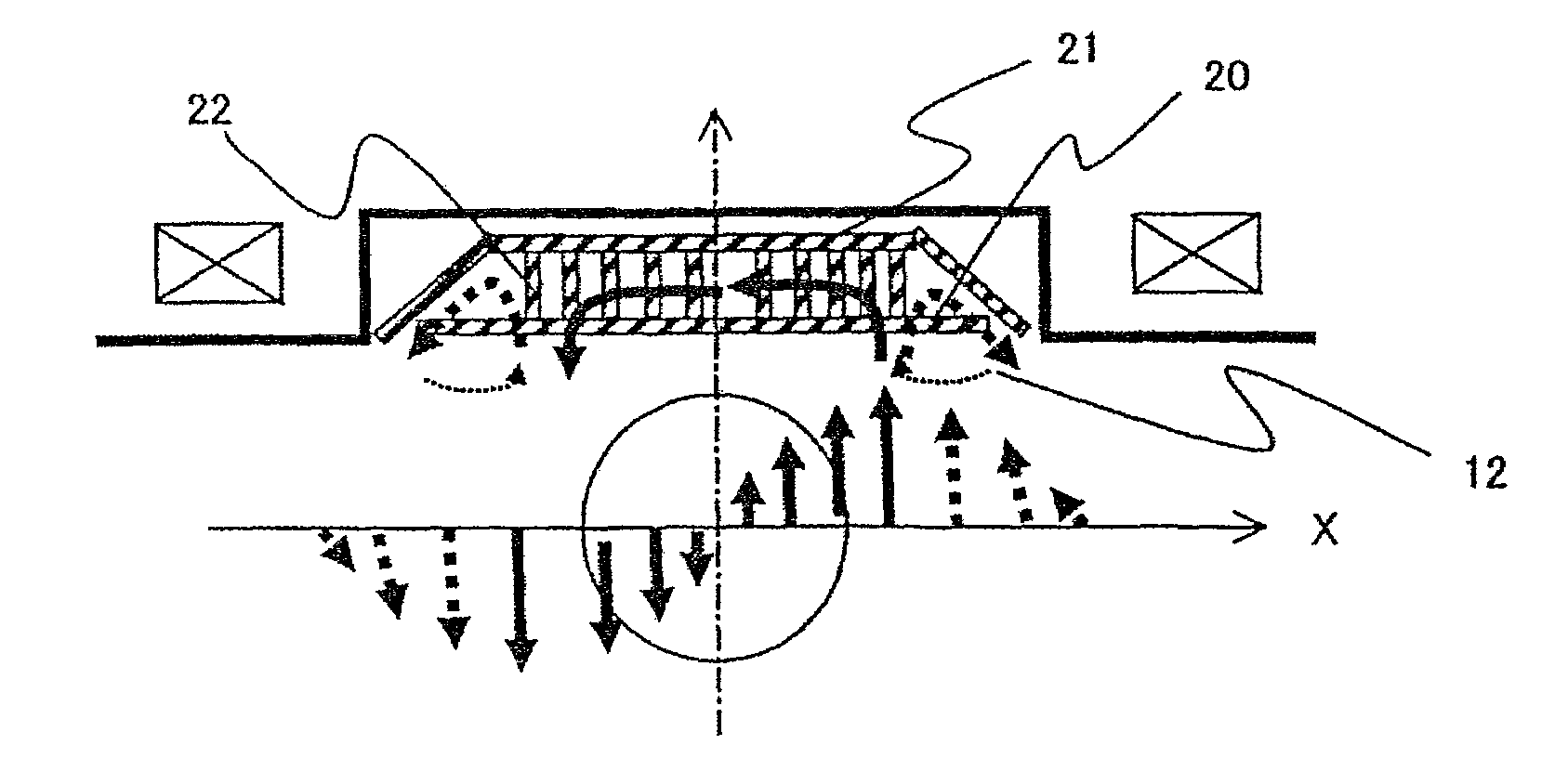
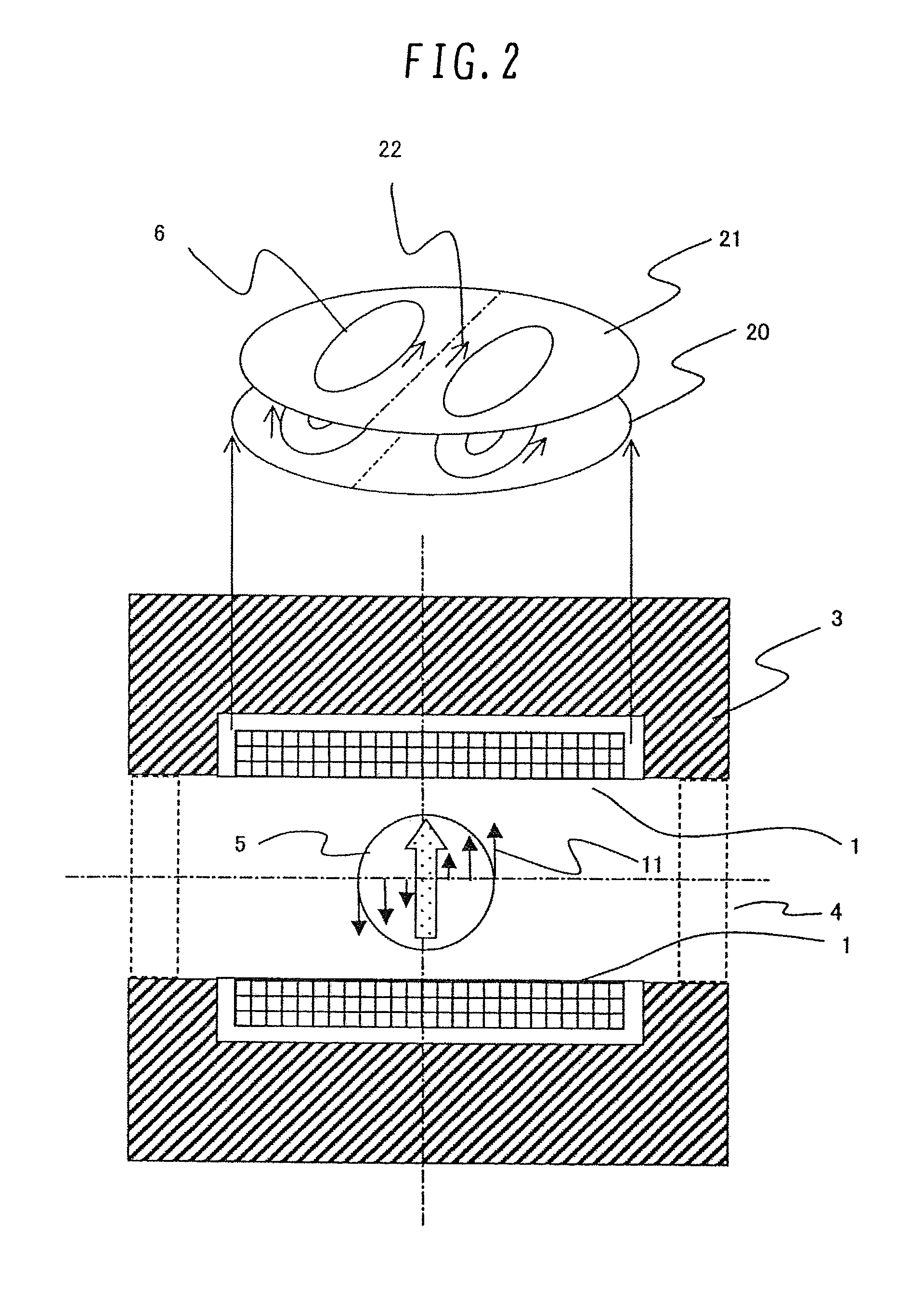
[0075]A description will be made of a second embodiment to which the gradient coil according to the present invention is applied with reference to FIG. 6. Since basic configurations of a gradient coil and an MRI apparatus according to the second embodiment are the same as those according to the first embodiment, a detailed description thereof is not provided. The shape of the gradient coil according to the second embodiment is different from that according to the first embodiment. FIG. 6 is a diagram showing the gradient coil according to the second embodiment. The gradient coil according to the second embodiment does not form a solenoidal coil in which conductor lines are wound between the shielded gradient coil 21 and the primary gradient coil 20. The gradient coil 1 having such a configuration is also capable of changing the direction of a magnetic line of force that is directed to the structural member (magnetic pole piece surface 9) located on the outside of the outer circumfer...

third embodiment

[0077]A description will be made of a third embodiment to which the gradient coil according to the present invention is applied. Since basic configurations of a gradient coil and an MRI apparatus according to the third embodiment are the same as those according to the first embodiment, a detailed description thereof is not provided. The gradient coil 1 according to the third embodiment is different from that according to the first embodiment in that the outer circumference of the shielded gradient coil 21 is not inclined toward the imaging area.

[0078]FIG. 7 is a diagram showing a winding structure, according to the present embodiment, in which the primary gradient coil 20 and the shielded gradient coil 21 are connected with each other. Specifically, FIG. 7 shows a detailed structure shown in FIG. 5B. Similarly to FIG. 1, a crossover between turns of conductive windings 6 is not illustrated. The gradient coil having the structure shown in FIG. 7 is also capable of reducing electromag...


PUM


Abstract

The gradient coil for a magnetic resonance imaging apparatus is adapted to encode information on a spatial position of a subject to be inspected into a nuclear magnetic resonance signal. The gradient coil includes a primary gradient coil and a shielded gradient coil. The primary gradient coil generates a gradient magnetic field in the imaging area. The shielded gradient coil is located on the side opposite to the imaging area relative to the primary gradient coil and cancels the gradient magnetic field generated by the primary magnetic field. The shielded gradient coil has a first area including a central axis perpendicularly extending through the central portion of the imaging area and a second area located on the side of the outer circumference of the first area. The second area is more inclined toward the imaging area than the first area.

Description

BACKGROUND OF THE INVENTION[0001]1. Field of the Invention[0002]The present invention relates to a gradient coil for a magnetic resonance imaging apparatus. In particular, the present invention relates to a gradient coil for a magnetic resonance imaging apparatus, which is capable of suppressing magnetic interactions with peripheral structures, and to a magnetic resonance imaging apparatus using the gradient coil.[0003]2. Description of the Related Art[0004]In a diagnosis using a nuclear magnetic resonance, the intensity of a magnetic field is associated with an area to be diagnosed. It is demanded that the intensity of a magnetic field generated by a magnet system vary within a range of about one millionth of the intensity of the magnetic field. Magnetic fields generated by the magnetic resonance imaging apparatus (hereinafter referred to as an MRI apparatus) are mainly divided into the following three types.[0005](1) Static magnetic field which is constant in terms of time and spa...

Claims


Application Information

Patent Timeline
IPC IPC(8): G01V3/00
CPCG01R33/4215G01R33/385
Inventor ABE, MITSUSHIIMAMURA, YUKINOBUYATSUO, TAKESHI
Owner FUJIFILM HEALTHCARE CORP
Why Eureka
Try Eureka