Dynamically-and continuously-variable rate, asynchronous data transfer

a data transfer and dynamic variable rate technology, applied in the field of asynchronous data transfer, can solve the problems of increasing the complexity and cost of the resulting system, the maximum transfer rate is limited to 16.666 khz baud, and the inability to synchronize over a continuous range of communication rates, etc., to achieve the effect of addressing excessive capacitance loading

Active Publication Date: 2009-08-18
AUSTIN STAR DETONATOR
View PDF31 Cites 19 Cited by
  • Summary
  • Abstract
  • Description
  • Claims
  • Application Information

AI Technical Summary

Benefits of technology

[0004]In the method of the present invention, which can be described as bit-asynchronous and half-duplex data transfer, the communication rate of data elements (such as “bytes” or “words”) is conveyed to the receiver without the need for any a priori or predetermined means (except for broad limits, e.g., 300 to 10000 baud, due to component / system limitations), by incorporating synchronization bits into the data. Such a packet may, for example, comprise a number of words in which each word contains bits of data plus some bits provided for timing synchronization. An initial synchronization word consisting solely of synchronization bits may also be included, and if so, can be used to determine the speed at which communication commences. The present invention thus allows a dynamically- and continuously-variable rate data transfer without the need for locally resetting the receiving device(s)' receiving frequencies or the need for a third clocking line as in a typical synchronous system.

Problems solved by technology

On the other hand, synchronous systems, e.g., Philips Semiconductors' “I2C bus,” are known, but such systems of course require a separate dedicated clock line, adding to complexity and cost of the resulting system.
However, in this system, the maximum transfer rate is limited to 16.666 kHz baud.
Finally, the Universal Serial Bus protocol (USB) utilizes an initial 8-bit synchronization portion in a serial data packet, but USB is only bi-modal and is not capable of synchronization over a continuous range of communication rates.
USB also does not contain any subsequent synchronization bits that are conveyed “mid-stream” within a serial packet, so it does not permit the accommodation of any timing skew that could occur in lengthy packets.
Timing skew within packets can be particularly problematic under various system conditions such as excessive capacitance loading or varying line voltages or current levels.

Method used


Image

  • Dynamically-and continuously-variable rate, asynchronous data transfer
  • Dynamically-and continuously-variable rate, asynchronous data transfer
  • Dynamically-and continuously-variable rate, asynchronous data transfer

Examples


Embodiment Construction

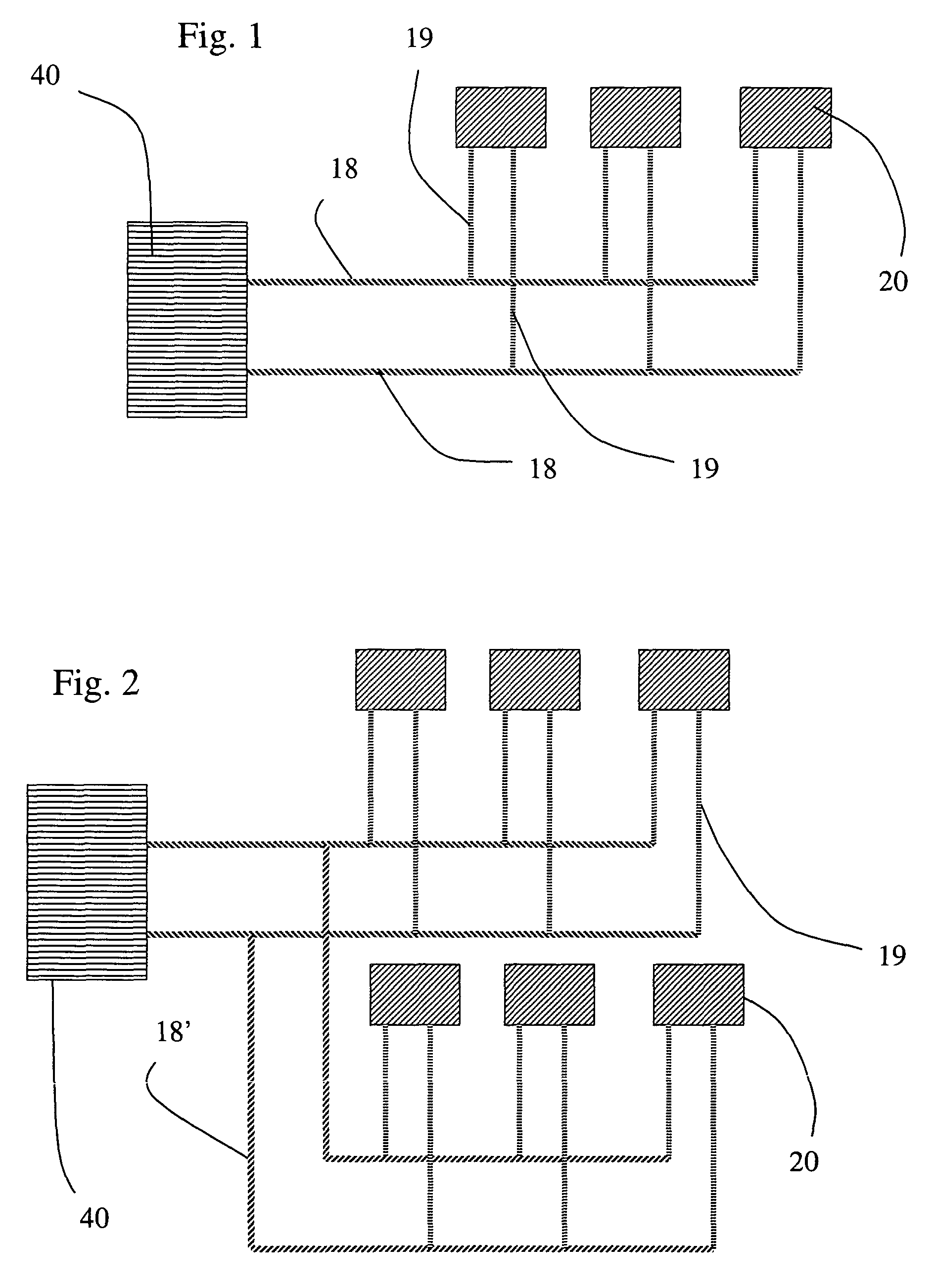
[0020]To describe the present invention with reference to the details of a particular preferred embodiment, it is noted that the present invention may be employed in an electronic system comprising a network of slave devices, for example, an electronic blasting system in which the slave devices are electronic detonators. As depicted in FIG. 1, one embodiment of such an electronic blasting system may comprise a number of detonators 20, a two-line bus 18, leg wires 19 including connectors for attaching the detonator to the bus 18, a logger (not shown), and a blasting machine 40. The detonators 20 are preferably connected to the blasting machine 40 in parallel (as in FIG. 1) or in other arrangements including branch (as in FIG. 2), tree, star, or multiple parallel connections. A preferred embodiment of such an electronic blasting system is described below, although it will be readily appreciated by one of ordinary skill in the art that other systems or devices could also be used, and m...


PUM


Abstract

A method of dynamically- and continuously-variable rate asynchronous data transfer, such as for use in an electronic blasting system, may employ a device that transmits data including synchronization bits and bits conveying other information, and a device that ascertains the rate of transmission of the synchronization bits and receives the bits conveying the other information at the ascertained rate of transmission.

Description

BACKGROUND OF THE INVENTION[0001]The present invention is directed generally to asynchronous data transfer, and more particularly, to a dynamically and continuously-variable rate asynchronous data transfer, such as for use in an electronic blasting system.[0002]In the prior art electronic blasting systems, the rate of communication between the blasting machine and the detonators has been fixed (by hardware and / or software) at both the transmitter and receiver portions, thus precluding a change to the communication rate if so desired to accomplish or optimize data transmission. On the other hand, synchronous systems, e.g., Philips Semiconductors' “I2C bus,” are known, but such systems of course require a separate dedicated clock line, adding to complexity and cost of the resulting system.[0003]It is also known for a slave device(s) to use the falling edge of a signal from the master device to synchronize the slave device(s)' internal timing circuitry based on time-slotting, as for ex...

Claims


Application Information

Patent Timeline
Patent Type & Authority Patents(United States)
IPC IPC(8): G06F15/173F42D1/05H04L1/00H04L7/04H04L25/02
CPCF42D1/05H04L25/0262H04L7/04
Inventor TEOWEE, GIMTONGKOUZNETSOV, ALEX A.
Owner AUSTIN STAR DETONATOR
Why Eureka
Try Eureka