Check patentability & draft patents in minutes with Patsnap Eureka AI!

Valve arrangement for vibration decoupling, which can be connected between a master cylinder and a slave cylinder of a hydraulic force transmission system

a technology of hydraulic force transmission system and valve arrangement, which is applied in the direction of valve details, couplings, mechanical equipment, etc., can solve the problems of increasing the force to be applied to the clutch pedal for rapid operation, the form of damping is subject to relatively tight restrictions, and the clutch pedal vibrates, etc., to reduce the “excess” of the pressure amplitude running through the valve arrangement. , the effect of reducing vibration

Active Publication Date: 2009-08-25
FTE AUTOMOTIVE GMBH & CO KG
View PDF18 Cites 12 Cited by
  • Summary
  • Abstract
  • Description
  • Claims
  • Application Information

AI Technical Summary

Benefits of technology

The valve arrangement effectively decouples vibrations between the master and slave cylinders, maintaining low fluid displacement resistance and preventing vibration transmission, thereby improving clutch pedal return rate and reducing perceivable vibrations for the driver, regardless of temperature.

Problems solved by technology

In such hydraulic clutch control systems, which can be considered as quasi-stationary hydraulic force transmission systems in which there is no continuous flow of hydraulic fluid, the problem arises that vibrations from the internal combustion engine or the crankshaft are transmitted to the clutch pedal via the clutch pressure plate, the clutch release mechanism, the clutch release bearing and the fluid column in the pressure line between the slave cylinder and the master cylinder, so that the clutch pedal vibrates in a way that can be perceived by the driver when he presses it down to release the clutch.
However, this form of damping is subject to relatively tight restrictions, since the described measures also give rise to an undesirable increase in the force to be applied to the clutch pedal for rapid operation, particularly at low temperatures.
The rate of return of the clutch pedal also decreases undesirably when these measures are used, again particularly at low temperatures, since the hydraulic medium—usually brake fluid—is already relatively viscous here.
On the one hand, considerable friction losses are associated with the sealing element provided on the outer circumference of the first valve body, and this may have a negative effect in particular on the rate of return of the clutch pedal.
On the other hand, at the end of the clutch engagement operation, there may be a considerable delay before the previously known valve arrangement develops its vibration-reducing effect: Once the fluid column has been pushed back from the slave cylinder in the direction of the master cylinder when the valve arrangement is opened, the first spring element gives rise to a resetting movement of the first valve body in the first direction, that is to say in the direction of the stop integral with the housing.

Method used


Image

  • Valve arrangement for vibration decoupling, which can be connected between a master cylinder and a slave cylinder of a hydraulic force transmission system
  • Valve arrangement for vibration decoupling, which can be connected between a master cylinder and a slave cylinder of a hydraulic force transmission system
  • Valve arrangement for vibration decoupling, which can be connected between a master cylinder and a slave cylinder of a hydraulic force transmission system

Examples


Embodiment Construction

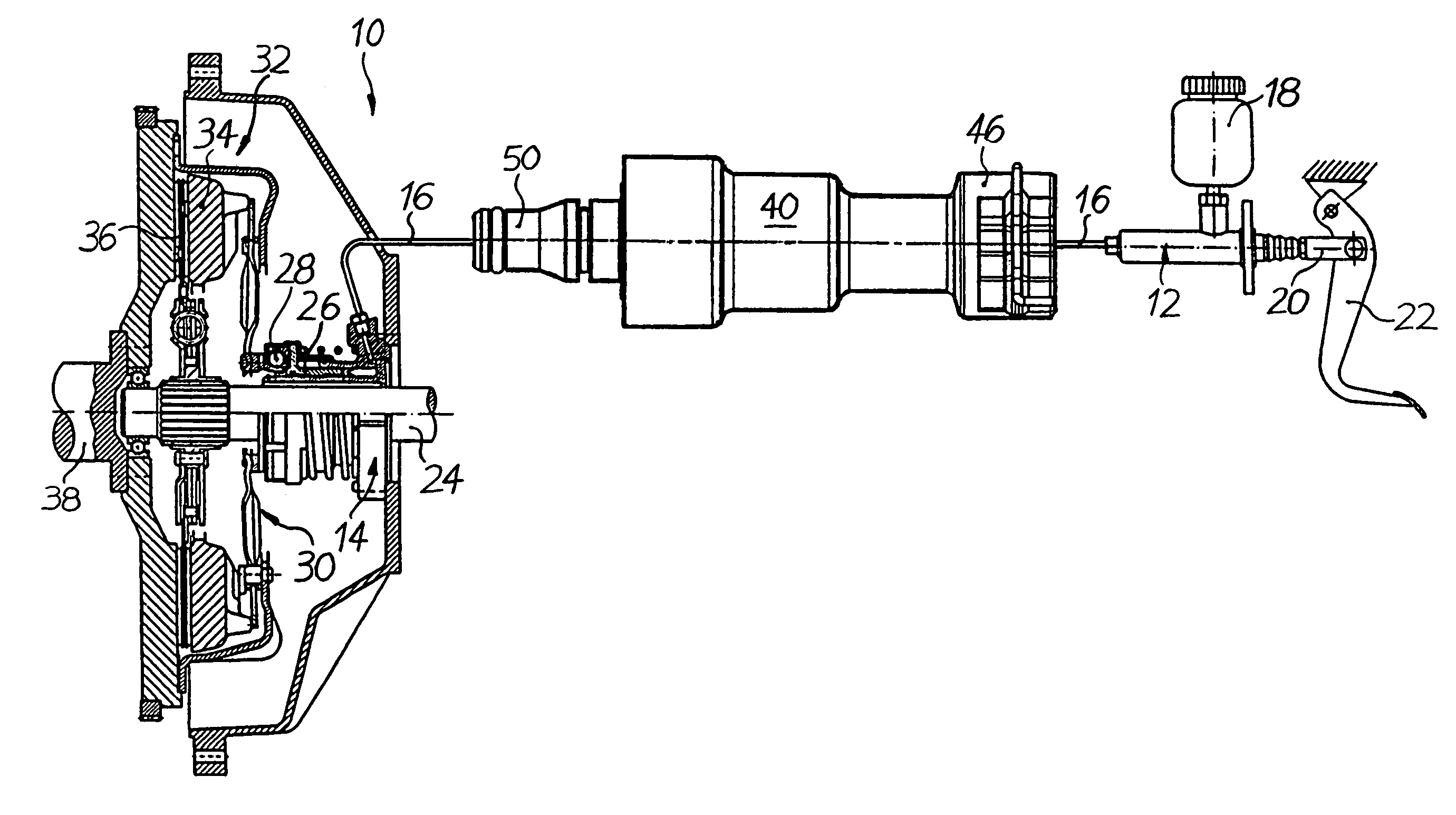
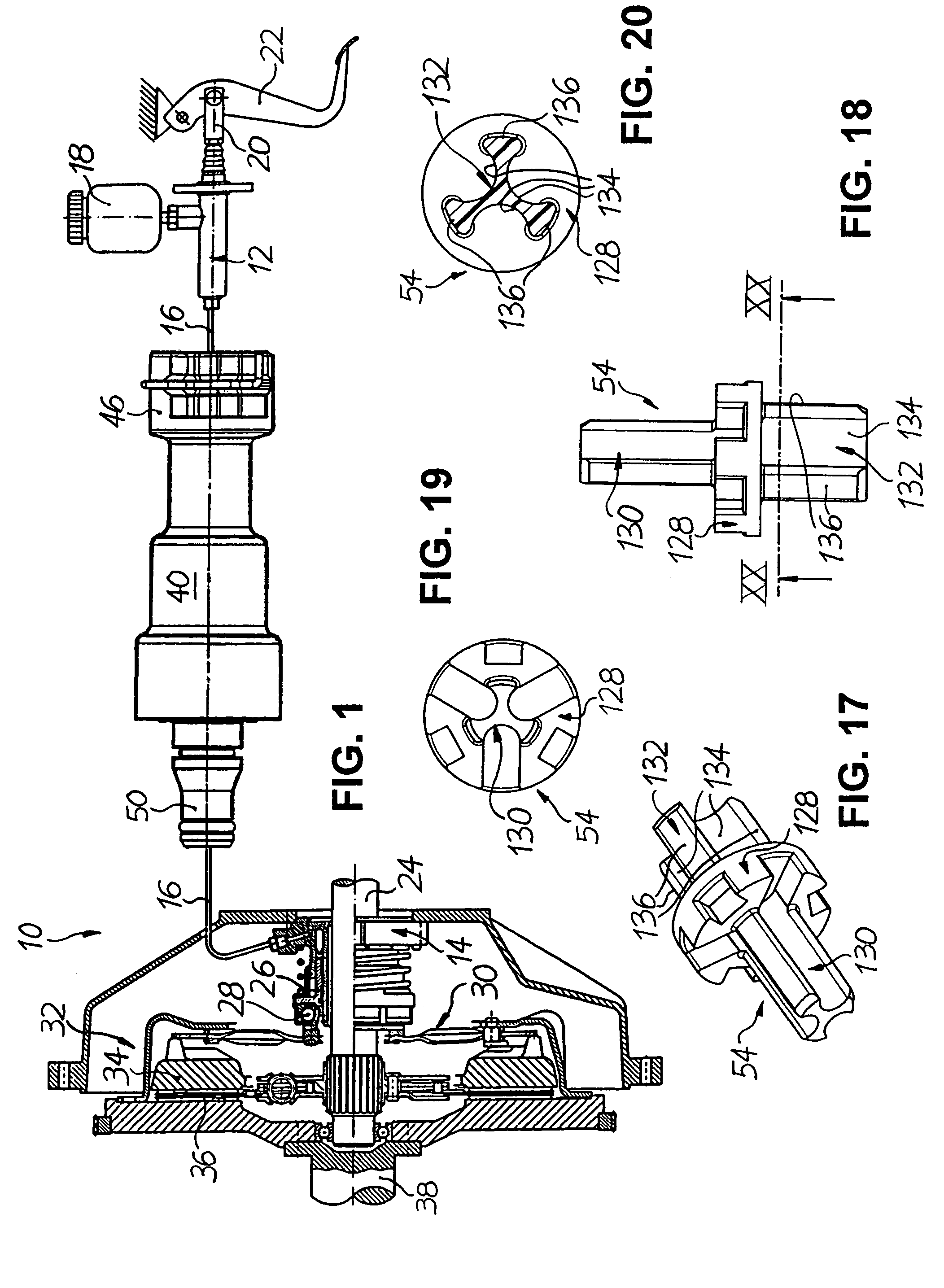
[0052]FIG. 1 shows, by way of example of a hydraulic force transmission system, a hydraulic clutch control system 10 for motor vehicles, which in a manner known per se comprises a master cylinder 12 and a slave cylinder 14 which are hydraulically connected to one another via a hydraulic line 16. The piston (not shown) of the master cylinder 12 connected to a compensating container 18 is actively connected via a piston rod 20 to a clutch pedal 22, so that the master cylinder 12 can be actuated by pressing down on the clutch pedal 22. In the process, a fluid column is pushed through the hydraulic line 16 in the direction of the slave cylinder 14, said fluid column hydraulically acting on the slave cylinder 14. The slave cylinder 14, in the illustrated example of embodiment an annular cylinder which is also referred to as the “central clutch release” on account of its concentric arrangement with respect to a gear shaft 24, more specifically the annular piston 26 thereof, is in active c...


PUM


Abstract

A valve arrangement for vibration decoupling has a housing, in which two valve bodies are accommodated, a first of which is biased by a spring in a reference direction towards a stop integral with the housing and has a through-path for fluid. The other housing is biased by a spring in an opposite direction towards a valve seat on the first valve body and lifts away from the latter in the event of a volume flow in the reference direction, so as to open the through-path for fluid. A further through-path for fluid is provided between the first valve body and the housing, wherein a further valve seat is formed on the stop integral with the housing, towards which further valve seat the first valve body is biased by a spring and lifts away from the valve seat in the event of a volume flow in the opposite direction.

Description

TECHNICAL FIELD[0001]The present invention relates to a valve arrangement for vibration decoupling, which can be connected between a master cylinder and a slave cylinder of a hydraulic force transmission system, and to the use thereof in a hydraulic force transmission system. In particular, the invention relates to a valve arrangement of the type widely used in hydraulic clutch control systems for motor vehicles.PRIOR ART[0002]A conventional hydraulic clutch control system comprises a master cylinder which can be actuated via a clutch pedal and is connected to a compensating container. The master cylinder is hydraulically connected to a slave cylinder via a pressure line, so that the pressure generated in the master cylinder by pressing down on the clutch pedal can be transmitted to the slave cylinder via the fluid column in the pressure line. As a result, the release bearing of the clutch is acted upon by the slave cylinder with an actuating force, so as, via a clutch release mecha...

Claims


Application Information

Patent Timeline
Patent Type & Authority Patents(United States)
IPC IPC(8): F16D25/12F15B7/06F16K47/00
CPCF15B7/00F16D48/02F15B21/008F16D2048/0215F16D2300/22F16D25/082F16D25/14
Inventor GEBERT, STEFANKOPP, MATTHIASSCHNEIER, JOCHENMULLER, OSWALD
Owner FTE AUTOMOTIVE GMBH & CO KG
Features
  • R&D
  • Intellectual Property
  • Life Sciences
  • Materials
  • Tech Scout
  • Unparalleled Data Quality
  • Higher Quality Content
  • 60% Fewer Hallucinations
Learn More