Method, apparatus, and system for driving LED's

a technology of led backlighting and led light, which is applied in the direction of pulse generators, pulse techniques, instruments, etc., can solve the problems of flickering observed by the human eye, inefficient power delivery based on losses, and the use of led backlight units also presents challenges

Inactive Publication Date: 2009-08-25
APPLIED CONCEPTS
View PDF29 Cites 73 Cited by
  • Summary
  • Abstract
  • Description
  • Claims
  • Application Information

AI Technical Summary

Problems solved by technology

Although there are certain advantages, the use of LED backlight units also present challenges with respect to thermal management, diffusion of point source light, driving, and control to provide the required performance.
In order to maintain the proper current balance in this arrangement for each parallel bank, however, it is necessary to provide a series dropping resistor between each of the banks, which leads to inefficient power delivery based on the losses across these resistors.
However, operating the LED or series connection of LED's at relatively low current (e.g., 1 to 10% of full output brightness) can result in luminous instability, which in turn results in flickering observed by the human eye.
Accordingly, while varying the amplitude of the constant current will be effective to accomplish dimming over the majority of the desired range, dimming at the lowest levels will be compromised.

Method used


Image

  • Method, apparatus, and system for driving LED's
  • Method, apparatus, and system for driving LED's
  • Method, apparatus, and system for driving LED's

Examples


Embodiment Construction

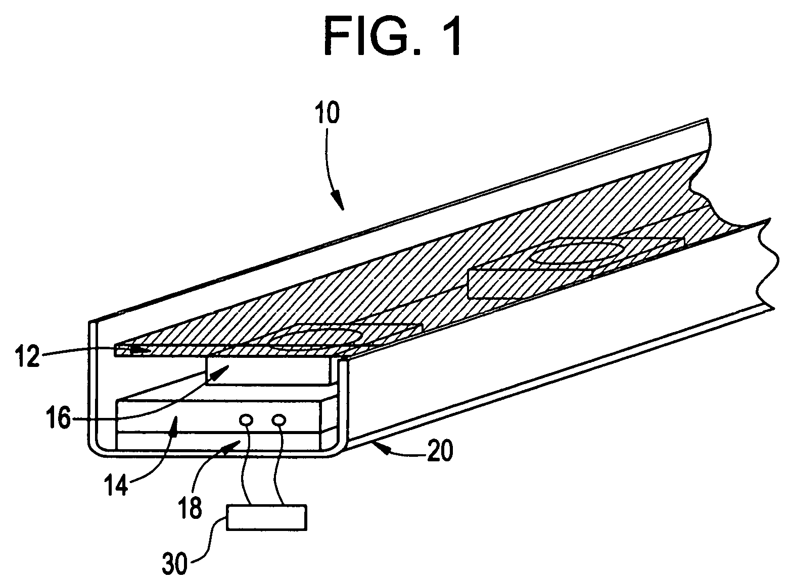
[0013]FIG. 1 shows an LED backlight unit 10 that can be used to provide edge lighting for a LCD display. The main components of the LED backlight unit 10 include the window 12, printed circuit board 14, LED's 16, and thermal conductive material 18. The LED backlight unit 10 is configured so as to fit within the edge rail housing 20 of the backlight light source. Alternatively, the LED backlight unit 10 can also include the edge rail housing 20. The window 12 may be of a clear or opaque material or may be a specialized optical element providing the required light focusing and diffusion. The printed circuit board 14 provides the mounting surface for the LED's 16 and can be configured to allow the thermal material 18 to contact the underside of the LED's 16. A connector 30 for interfacing with an LED driver 40 to provide the necessary voltage and current is connected to the printed circuit board 14. The thermal conductive material 18 provides the necessary thermal interface between the...


PUM


Abstract

A method and apparatus for driving LED's is disclosed, comprising the steps of receiving a desired intensity value, wherein the desired intensity value represents the desired intensity for the LED's; generating a first switching control signal, wherein the first switching control signal is a pulse width modulated signal whose duty cycle is based on the desired intensity value; switching the LED's on and off based on the first switching control signal, wherein the switching takes place when the desired intensity value is less than a first desired intensity value threshold; generating a desired constant current value based on the desired intensity value, wherein the desired constant current value represents the value of the desired constant current to drive the LED's; determining an actual constant current value, wherein the actual constant current value represents the value of the actual constant current driving the LED's; comparing the actual constant current value with the desired constant current value; and adjusting the output of the primary drive of the LED's so that the actual constant current value is equal to the desired constant current value. A system for providing LED backlighting of a display is also disclosed, comprising a first constant current source driver, wherein the constant current source driver comprises a primary drive and a step-up circuit; a first series connection of LED's, wherein the LED's are driven by the first constant current driver; and wherein the first constant current source provides a forward voltage of 42 volts or greater to drive the first series connection of LED's.

Description

BACKGROUND OF THE INVENTION[0001]This invention generally relates to light emitter diode (LED) backlighting of liquid crystal displays (LCD), including the driving and control of those LED's.[0002]LCD displays comprise a significant percentage of the market for display sizes large and small, including displays for cash registers, product dispensers, gas pumps, computer displays (laptop and stand alone), and flat panel televisions. The lighting for these LCD displays is typically provided by a backlight unit installed underneath a display panel, wherein the backlight unit includes one or more light sources and a light diffusion means for providing a uniformly distributed light source. Depending on the position of the light source(s), backlight units can be categorized as either edge type or direct type. Edge type backlight units typically consist of one or more edge rails where the light sources are located.[0003]A significant percentage of backlight units for LCD displays use cold c...

Claims


Application Information

Patent Timeline
Patent Type & Authority Patents(United States)
IPC IPC(8): G05F1/00
CPCH05B33/0803H05B33/0821H05B33/0815Y02B20/347H05B45/40H05B45/37Y02B20/30H05B45/325H05B45/345H05B45/382H05B45/39H05B45/10
Inventor SOOS, STEPHEN C.
Owner APPLIED CONCEPTS
Why Eureka
Try Eureka