System and method for determining angular position and controlling rotor orientation

a technology of angular position and rotor, which is applied in the direction of motor/generator/converter stopper, dynamo-electric converter control, instruments, etc., can solve the problems of inability to provide accurate rotor position sensing, inability to adapt other motors to utilize sensorless technologies, and inability to solve the problem of prohibitively expensive solutions

Active Publication Date: 2009-08-25
RAYTHEON CO
View PDF10 Cites 12 Cited by
  • Summary
  • Abstract
  • Description
  • Claims
  • Application Information

AI Technical Summary

Problems solved by technology

Some motors use sensorless technologies, but these technologies generally do not provide accurate rotor position sensing at low speeds and are not smooth on startup of the motor.
Other motors are not adapted to utilize sensorless technologies and must incorporate a rotor position sensing mechanism.
Depending on the resolution required, these solutions may be prohibitively expensive within applications that require low cost motors.
One disadvantage of resolvers is that they operate on the principle of inductive coupling of magnetic fields which are modulated and subsequently demodulated into sine and cosine components.
The processes involved with coupling the magnetic fields and modulation and demodulation limit the resolver's useful speed range.
As with encoders, resolvers are precision built, commercially available sensing devices that may be fragile and expensive, requiring complex encoding / decoding circuitry and bulky and heavy magnetic components.
At the same time, these drive methods do not generally provide ripple-free torque from the motor.
This may be unacceptable in a variety of applications.
Thus, the approach described therein does not lend itself to scalable applications in terms of device dimensions, placement of sensors, accuracy of angular measureiment—and notably—the discrete hardware implementation of obtaining angular position data.
While useful in certain applications, conventional servomechanism sensing and control devices have a number of disadvantages, including, for example, the inherent volume exclusion of the devices themselves, ease of manufacture, cost and accuracy of angular position measurements.
These characteristics tend to limit the design flexibility and commercial feasibility of conventional sensor systems.

Method used


Image

  • System and method for determining angular position and controlling rotor orientation
  • System and method for determining angular position and controlling rotor orientation
  • System and method for determining angular position and controlling rotor orientation

Examples


embodiment 100

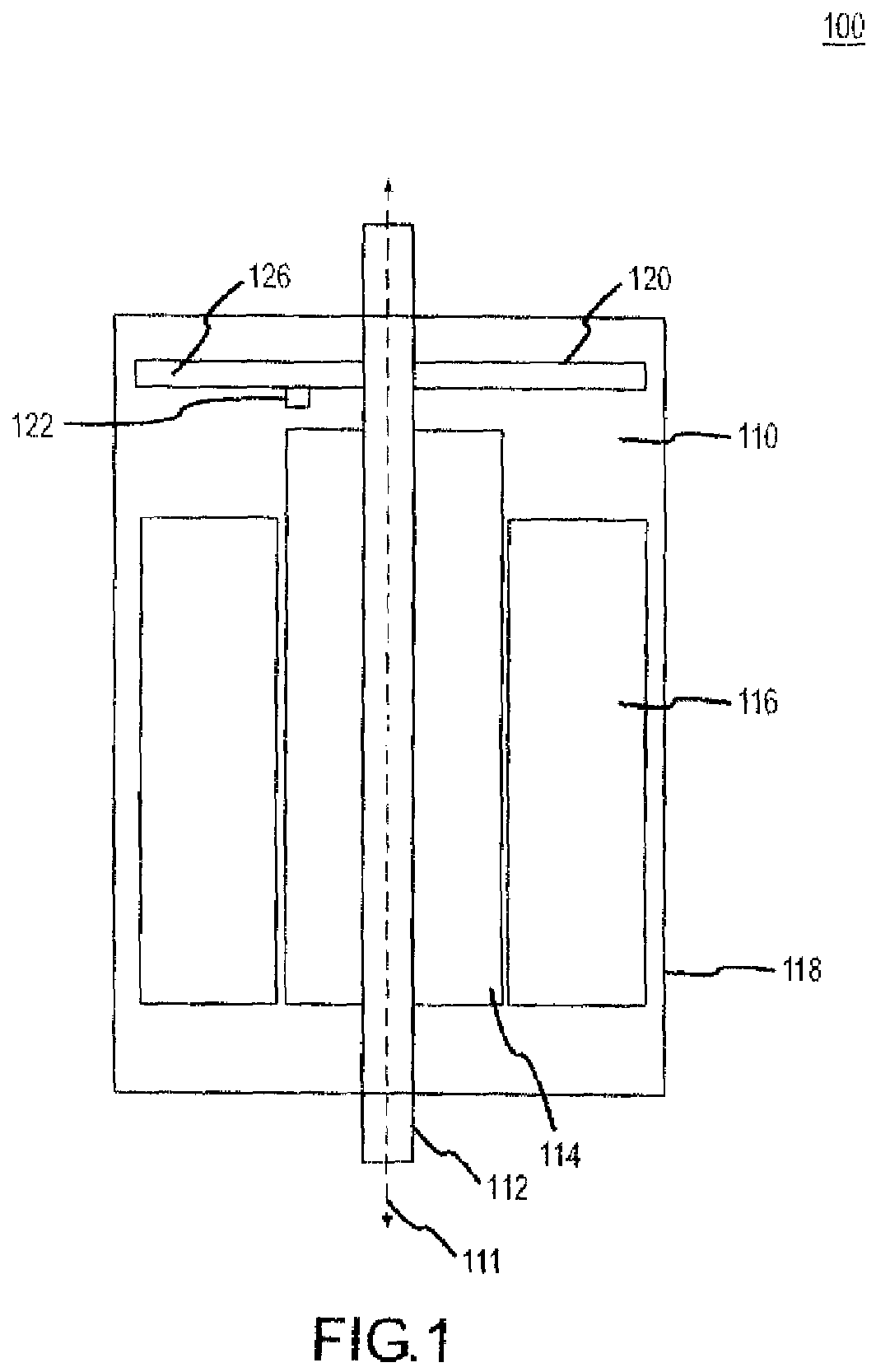
[0032]As generally depicted in FIG. 1, a representative embodiment 100 of the present invention provides a side view of motor 110 and circuit card 120 in which the circuit card 120 is configured to produce a signal in response to a change in the rotational position of rotor 112. Motor 110 may comprise rotor shaft 112, motor field pole magnets 114, stator 116, and housing 118. Rotor shaft 112 may be configured to rotate about its principal axis 111 within housing 118 in response to the rotating magnetic field of stator 116 and the effect of this field on motor field pole magnets 114. Circuit card 120 may comprise a sensor module 122 coupled to circuit card body 126. Sensor module 122 may be configured to produce a signal in response to rotation of rotor shaft 112 and communicate this signal to a position determination module.

[0033]Motor 110 may be configured to convert electrical energy into kinetic energy. Alternatively, conjunctively or sequentially, motor 110 may be suitably confi...

embodiment 400

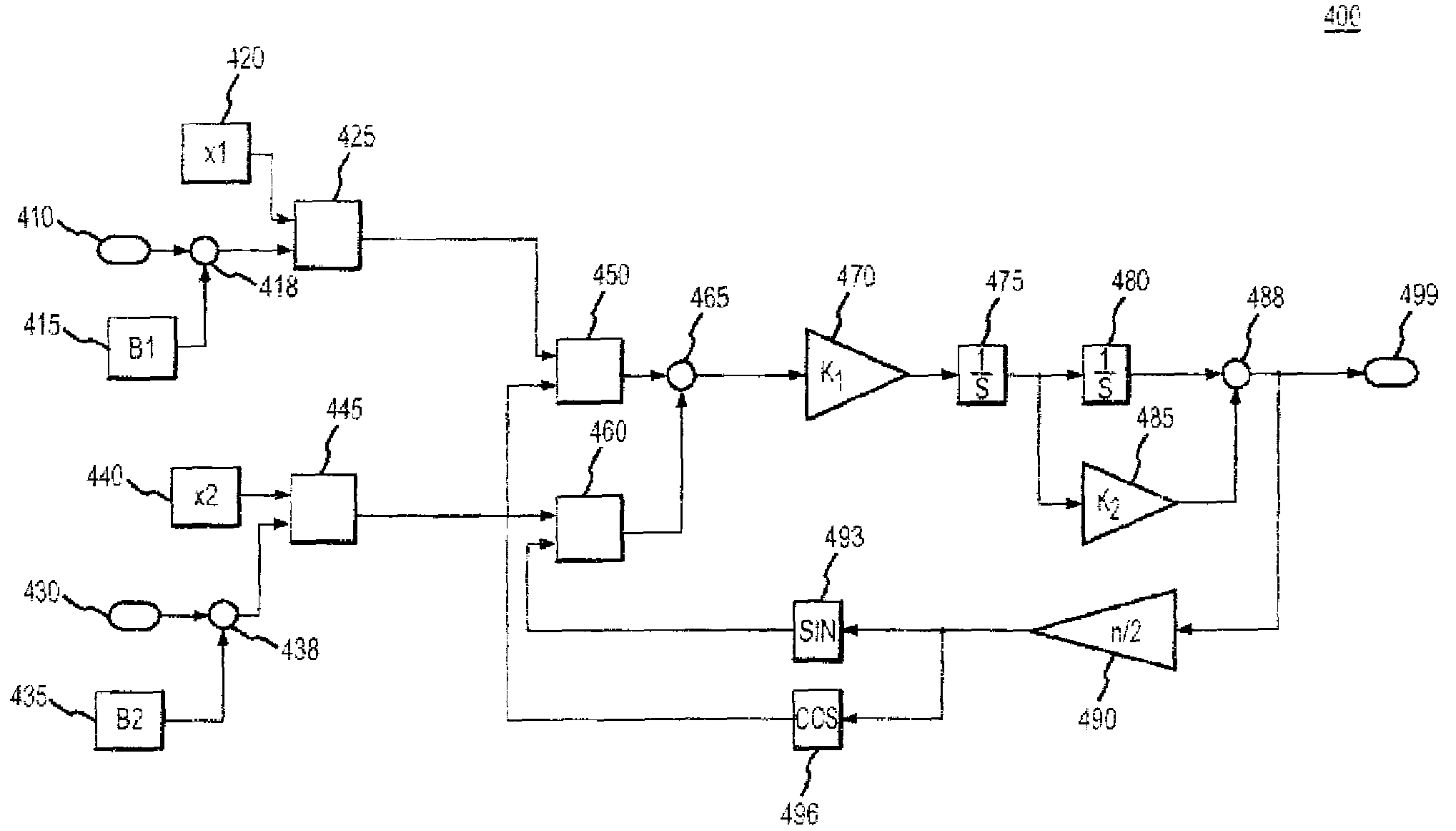
[0053]A representative embodiment of the position determination module 335 as shown in FIG. 3, is depicted in FIG. 4. The representative embodiment 400 provides a system for processing sensor module output via a recursive frequency domain function. A representative recursive frequency domain function may comprise the steps of producing a signal from a pair of HEDs, scaling the signals, and applying a mathematical error operator on the scaled HED signals and the previous estimated position in order to re-iterate the estimated position.

[0054]In a representative embodiment, sensor module may comprise a first HED and a second HED. The first HED may produce a first signal 410 and the second HED may produce a second signal 430. First signal 410 may be adjusted by an offset factor 415 and a scale factor 420. Likewise, second signal 430 may be adjusted by an offset factor 435 and a scale factor 440.

[0055]Processing of the first signal 410 and the second signal 430 may proceed in accordance ...


PUM


Abstract

Methods and devices for determining the position and / or angular orientation of a rotating shaft. Exemplary features include a sensor module and a position determination module. Sensor module may include a plurality of Hall Effect devices (HEDs) arranged at a specified angular separation to produce a signal in response to rotation of the shaft. Position module may be responsive to sensor module to produce a converted signal, determine an error term, and produce a position estimate. Converted signal may be produced by processing the HED signals into sinusoidal reference signals having offset scale and amplitude scale factors. Error term may be determined by processing the converted signals to produce an estimated position signal. Position estimate may be produced by processing the error term. Refined position measurement may be achieved by iterative elimination of regressive differences between position estimates with minimization of absolute magnitude of error term.

Description

RELATED APPLICATIONS[0001]This application claims the benefit of U.S. Provisional Patent Application No. 60 / 759,464 (filed on Jan. 17, 2006) entitled “System And Method To Use Linear Hall Effect Devices For Determining Angular Position For High Performance Servo Control”.FIELD OF INVENTION[0002]The present invention generally concerns systems and methods for measuring or actuating angular position in rotating systems; and more particularly, representative and exemplary embodiments of the present invention generally relate to systems, devices and methods for the determination and control of the angular position or orientation of a rotor assembly.BACKGROUND OF INVENTION[0003]Servomechanisms are generally implemented across a broad spectrum of industries. Such devices typically make use of a sensor to produce output in response to movement of a rotor shaft and a microprocessor to convert the sensor output into a useful metric. In particular, the sensor featured in such applications may...

Claims


Application Information

Patent Timeline
Patent Type & Authority Patents(United States)
IPC IPC(8): H02P6/16
CPCG01R33/0029H02P6/16H02P6/142H02P6/15
Inventor ROBICHAUX, JERRY D.BUGGE, JOHN F.DE LAIR, CHARLESLAFONTAINE, ERIC M.
Owner RAYTHEON CO
Why Eureka
Try Eureka