Optical device and display operating in two dimensional and autostereoscopic three dimensional modes

a technology of optical devices and display screens, applied in the field of optical devices, can solve the problems of light paths that can interfere with each other, variation in brightness in the 2d mode across the display, etc., and achieve the effect of reducing crosstalk and improving the achromaticity of bright and dark states

Inactive Publication Date: 2009-08-25
SHARP KK
View PDF7 Cites 27 Cited by
  • Summary
  • Abstract
  • Description
  • Claims
  • Application Information

AI Technical Summary

Benefits of technology

[0035]Throughout the present specification, positive values of angles may be either clockwise or anticlockwise, with negative values then referring to angles in the opposite direction. Also, all angles of polarisation directions and retarder slow axes are expressed “modulo 180°”. Thus, each angle θ is equivalent to each angle (θ+n·180)°, where n is any integer. However, in the cases of certain devices, because of the nature of their constructions, a value of θ may be preferred over the value (θ+180°) because of improved performance.
[0036]It is thus possible to provide an optical device which is suitable for use in displays. When used, for example, in an autostereoscopic 3D display which also has a 2D mode of operation, such a device substantially reduces or suppresses variations in light intensity across the display in the 2D mode. For example, where the device operates as a parallax barrier in the 3D mode, faint intensity strips, (corresponding to the barrier or slit regions in the 3D mode) are substantially suppressed in the 2D mode so that, as compared with known types of displays, this visual artefact can be removed or reduced to the point where it is not visible to an observer.
[0038]Achromaticity of bright and dark states can be improved. This results in reduced crosstalk in the 3D mode of operation.

Problems solved by technology

When a polariser is placed in the path, the polarisations are made the same and the light paths are able to interfere.
However, in general, there is a relative phase shift between the paths and so adding the amplituders (rather than the intensities) does not cancel out the variation.
This results in a variation in brightness in the 2D mode across the display and is undesirable.

Method used


Image

  • Optical device and display operating in two dimensional and autostereoscopic three dimensional modes
  • Optical device and display operating in two dimensional and autostereoscopic three dimensional modes
  • Optical device and display operating in two dimensional and autostereoscopic three dimensional modes

Examples


Embodiment Construction

[0067]Hereinafter, the present invention will be described by way of examples with reference to the drawings.

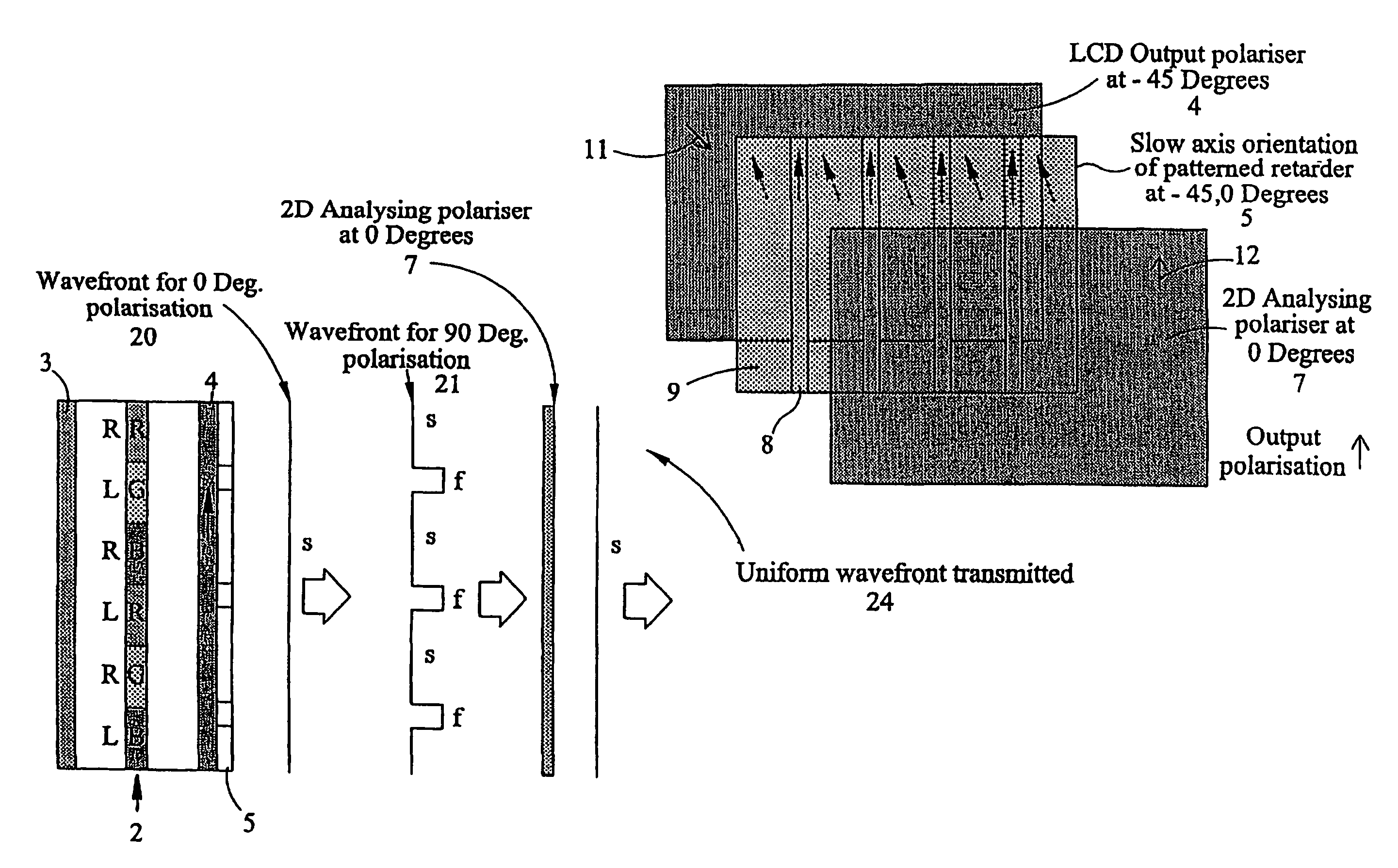
[0068]FIG. 6 illustrates an optical device constituting an embodiment of the invention and forming part of an autostereoscopic display, also constituting an embodiment of the invention and having an autostereoscopic 3D mode of operation and a 2D mode of operation. The 2D mode of operation is illustrated in FIG. 6 and, in this mode, the device and display of FIG. 6 differ from that of FIG. 5 in that the transmission axis 12 of the output polariser 7 is oriented at 45° to the transmission axis 11 of the polariser 4, which comprises an output polariser of a liquid crystal display (LCD) 2 forming a spatial light modulator.

[0069]Because liquid crystal devices are typically arranged with the transmission axis 11 of their output polarisers at −45° to the image vertical of the image displayed by such devices, this is the orientation which is illustrated in FIG. 6 and the other drawin...


PUM

PropertyMeasurementUnit
polarization rotationaaaaaaaaaa
refractive indexaaaaaaaaaa

Abstract

An optical device comprises an input polarizer 4, a patterned retarder 5 and an output polarizer 12. The retarder 5 has regions 8 and 9, at least one of which alters the polarization of light from the input polarizer 4. The output polarizer 7 has a transmission axis 12 such that light passing through the regions 8 and 9 of the retarder 5 and through the output polarizer 7 is matched in amplitude, phase and polarization. Such a device may be used as a switchable parallax barrier with an LCD 2 to provide a display which is switchable between an autostereoscopic 3D mode and a 2D mode with the 2D mode having more uniform intensity across the display.

Description

TECHNICAL FIELD[0001]The present invention relates to an optical device which may, for example, be used in a display capable of operating in two dimensional (2D) and autostereoscopic three dimensional (3D) modes. The present invention also relates to displays incorporating such optical devices.BACKGROUND ART[0002]GB 2 317 295 and EP 0 829 744 discloses a display which may be operated in 2D and 3D modes. FIG. 1 of the accompanying drawings illustrates the basic structure of one example of such a display in the 2D and 3D modes. In the 3D mode, the display comprises a compact extended backlight 1 disposed behind a spatial light modulator (SLM) embodied as a liquid crystal device (LCD) 2. The LCD 2 has a rear polariser 3 and a front polariser 4. In the 3D mode, the display is of the front parallax barrier type in which the parallax barrier is formed by a patterned retarder 5 formed on a substrate 6 and a polariser 7.[0003]In the 2D mode also illustrated in FIG. 1, the polariser 7 is rem...

Claims


Application Information

Patent Timeline
Patent Type & Authority Patents(United States)
IPC IPC(8): G02F1/1335G02F1/1333G02B5/30G02B30/25G02B30/31G02F1/13G02F1/13363G03B35/24H04N13/00H04N13/04
CPCG02B5/3083G02B27/2214H04N13/0454H04N13/0409H04N13/0411G02B27/26H04N13/312H04N13/31H04N13/359G02B30/25G02B30/31G02F1/13G02B30/27
Inventor JACOBS, ADRIAN MARC SIMONTILLIN, MARTIN DAVIDMONTGOMERY, DAVID JAMES
Owner SHARP KK
Why Eureka
Try Eureka