Rotary process for forming uniform material
a technology of uniform material and rotary process, which is applied in the direction of weaving, transportation and packaging, and other domestic objects, and can solve the problems of incongruity of web layers formed by conventional flash spinning processes
- Summary
- Abstract
- Description
- Claims
- Application Information
AI Technical Summary
Benefits of technology
Problems solved by technology
Method used
Image
Examples
example 1
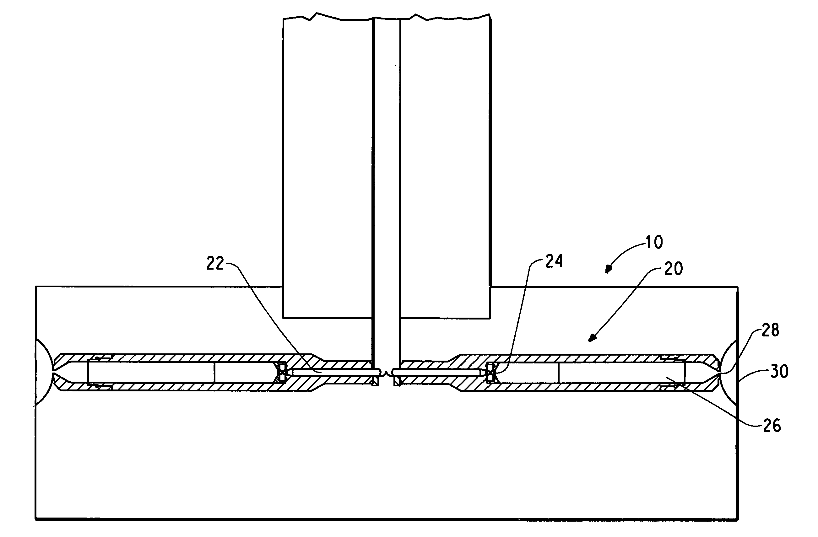
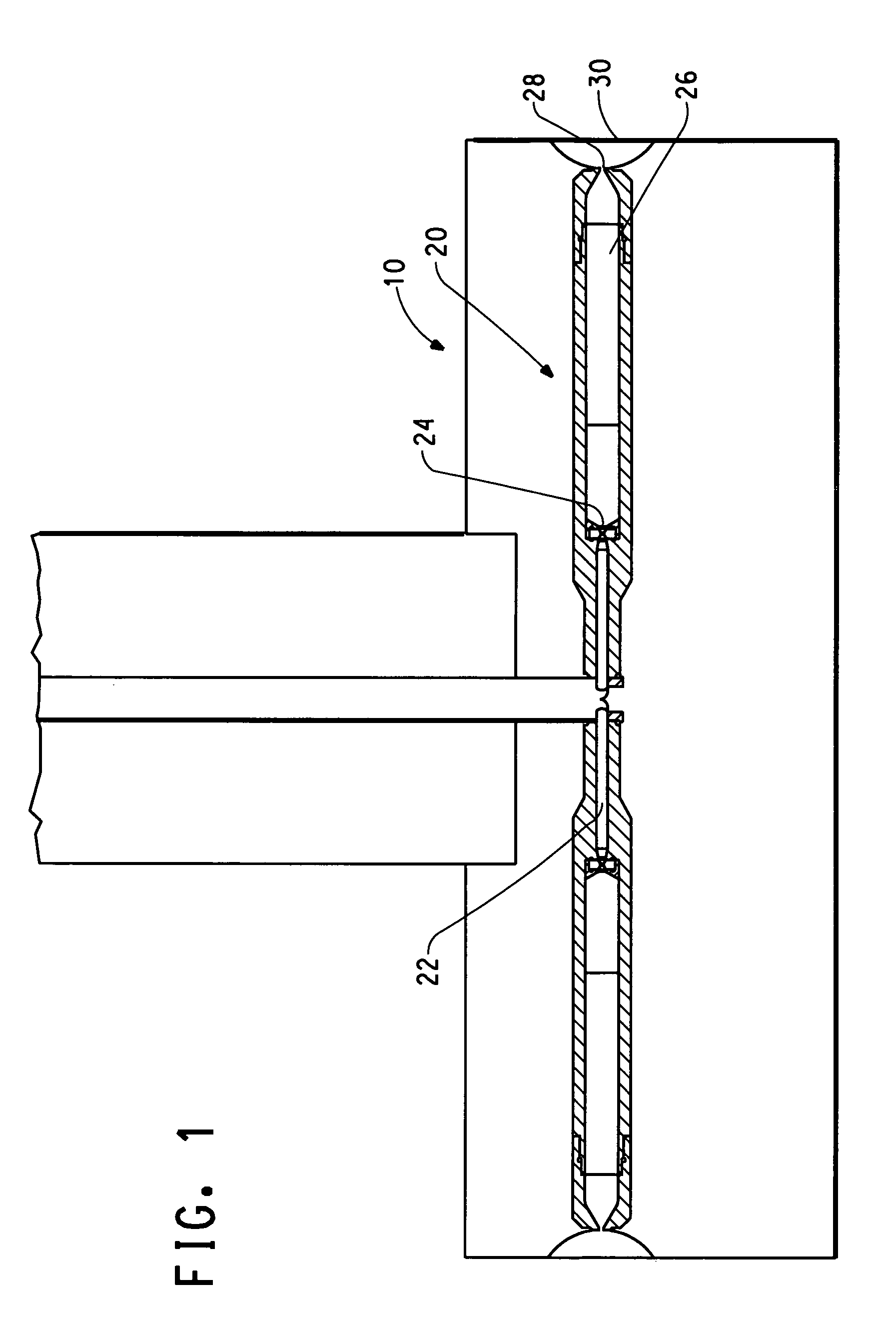
[0094]A membrane comprising discrete fibrils was formed by flash-spinning a polymeric solution of 1% Mat 8 high density polyethylene (HDPE) (obtained from Equistar Chemicals LP) in a spin agent of Freon® 11 trichlorofluoromethane (obtained from Palmer Supply Company) at a temperature of 190° C. and a filter pressure upstream of the letdown orifice of 2080-2200 psi (14-15 MPa) through a nozzle in a rotor rotating at 1000 rpm. The rotor used in Examples 1-4 and Examples 6-7 had a diameter of 16 inches (41 cm) and a height of 3.6 inches (9.2 cm). The nozzle used in Example 1 comprised a letdown orifice having a diameter of 0.025 inch (0.064 cm) and a length of 0.038 inch (0.096 cm) which opened to a letdown chamber. The letdown chamber led to a spin orifice having a diameter of 0.025 inch (0.064 cm) and a length of 0.080 inch (0.20 cm). The outlet slot of the nozzle was parallel with the axis of the rotor. The flash spun material was discharged from the nozzle in the radial direction a...
example 2
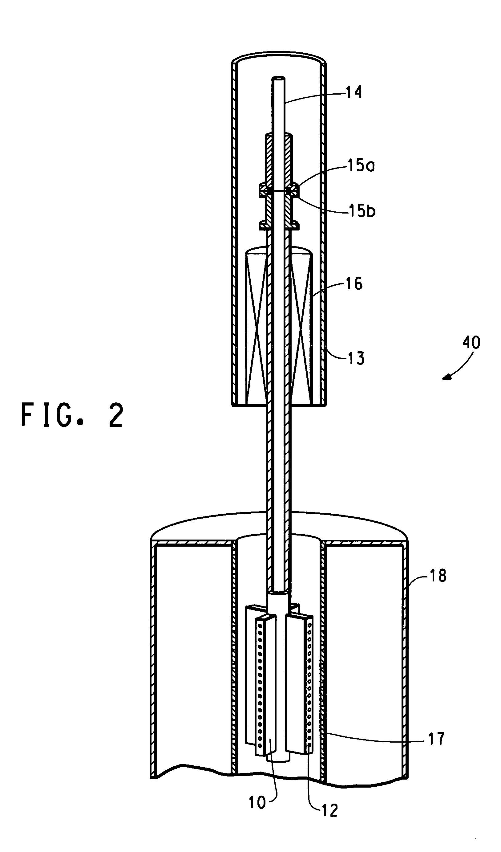
[0098]A membrane comprising discrete fibrils and polymer particles was formed by flash-spinning a 0.5% polymeric solution of 96% Mat 8 HDPE (obtained from Equistar Chemicals LP) and 4% blue HDPE in a spin agent of Freon® 11 trichlorofluoromethane (obtained from Palmer Supply Company) at a temperature of 170-180° C. and a filter pressure upstream of the letdown orifice of 2150-2200 psi (15 MPa) through a nozzle in a rotor rotating at 1000 rpm onto a leader sheet of white Sontara® fabric (available from E. I. du Pont de Nemours and Company) positioned on a porous collection belt. The nozzle comprised a letdown orifice having a diameter of 0.025 inch (0.064 cm) and a length of 0.080 inch (0.20 cm) which opened to a letdown chamber. The letdown chamber led to a spin orifice having a diameter of 0.025 inch (0.064 cm). The distance between the outlet of the nozzle and the collection belt was 1.5 inches (3.7 cm). The rotor was enclosed in a spin cell and the interior of the spin cell was m...
example 3
[0102]A membrane comprising discrete fibrils and polymer particles was formed by flash-spinning a polymeric solution of 4% Tefzel® ETFE (ethylene-tetrafluoroethylene copolymer) (available from E. I. du Pont de Nemours and Company) in a spin agent of Freon® 11 trichlorofluoromethane (obtained from Palmer Supply Company) at a temperature of 210° C. and a filter pressure upstream of the letdown orifice of 2160-2340 psi (15-16 MPa) through two nozzles having dimensions as described in Example 1 in a rotor rotating at 1000 rpm onto a leader sheet of Typar® fabric (available from E. I. du Pont de Nemours and Company) positioned on a porous collection belt. The outlet slots of the nozzles were oriented at angles of +20° and −20° relative to the axis of the rotor. The flash spun material was discharged from the nozzle in the radial direction away from the rotor. The distance between the outlet of the nozzle and the collection belt was 1 inch (2.5 cm). The rotor was enclosed in a spin cell a...
PUM
| Property | Measurement | Unit |
|---|---|---|
| temperature | aaaaa | aaaaa |
| temperature | aaaaa | aaaaa |
| thickness | aaaaa | aaaaa |
Abstract
Description
Claims
Application Information
 - R&D
- Intellectual Property
- Life Sciences
- Materials
- Tech Scout
- Unparalleled Data Quality
- Higher Quality Content
- 60% Fewer Hallucinations
Browse by: Latest US Patents, China's latest patents, Technical Efficacy Thesaurus, Application Domain, Technology Topic, Popular Technical Reports.
© 2025 PatSnap. All rights reserved.Legal|Privacy policy|Modern Slavery Act Transparency Statement|Sitemap|About US| Contact US: help@patsnap.com


