Data adaptation protocol

a data adaptation and protocol technology, applied in the field of communication systems, can solve the problems of not supporting n64 kbit/s transport, unable to ensure the same switching delay for all connections, and not supporting multiplexing of multiple connections within a cell, etc., to facilitate the orderly formatting and synchronized transmission

Active Publication Date: 2009-09-08
RIBBON COMM OPERATING CO INC
View PDF16 Cites 26 Cited by
  • Summary
  • Abstract
  • Description
  • Claims
  • Application Information

AI Technical Summary

Benefits of technology

[0017]The invention discloses an apparatus and technique that allows for both TDM to TDM time slot switching and TDM to packet time slot switching within a gateway using only a single packet switch. The packet switch performs all switching, including TDM to TDM and TDM to packet. Since a packet switch is inherently asynchronous and the data coming from the TDM domain is synchronous, special circuitry, referred to as Synchronous Aggregation Logic (SAL) facilitates the orderly formatting and synchronized transmission of synchronous data across the asynchronous switch. The gateway apparatus includes multiple network server cards which are synchronized with each other and the network to allow for time slot switching between a source server card and a destination server card. Synchronization logic generates a special clock signal defining a fixed number of synchronization intervals during which serial to parallel data conversion and subpacketization occur.
[0021]The destination time slot identifier data associated with a particular subpacket identifies which play-out buffer within an egress data RAM the subpacket is read into. The synchronization tag determines the position within the play-out buffer in which the subpacket will be written. In the illustrative embodiment, there are only four different synchronization intervals. Subpackets are read into a position of a respective play-out buffer with a two interval offset. For example, subpackets constructed during synchronization interval zero will be placed within a play-out buffer at synchronization interval two. In this manner, the subpackets are always played-out or converted from parallel data into serial synchronous data with a fixed delay, i.e., two synchronization intervals. In this manner, the system designer may optimize the number of synchronization intervals and the offset necessary for the synchronous data to be transported through the asynchronous medium. As a result, synchronous data from the ingress side is transported through an asynchronous switch and onto an egress side with a constant, fixed delay. As such the synchronocity of the data is maintained. The use of a synchronization tag at the source eliminates the need for context at the destination.

Problems solved by technology

SAL does not support splitting of subpackets among packets, but instead uses fixed-size subpackets that fit completely within a packet.
In addition, in the AAL1 protocol cells do not allow multiplexing of multiple connections within a cell, i.e., no subpackets.
SAL can be used over a wide area network, but cannot assure the same switching delay for all connections or support N×64 kbit / s transport.
The prior art allows constant delay for individual connections (via network clock, or adaptive clock or SRTS methods), but the delay is unknown and is not assured to be the same among connections.

Method used


Image

  • Data adaptation protocol
  • Data adaptation protocol
  • Data adaptation protocol

Examples


Embodiment Construction

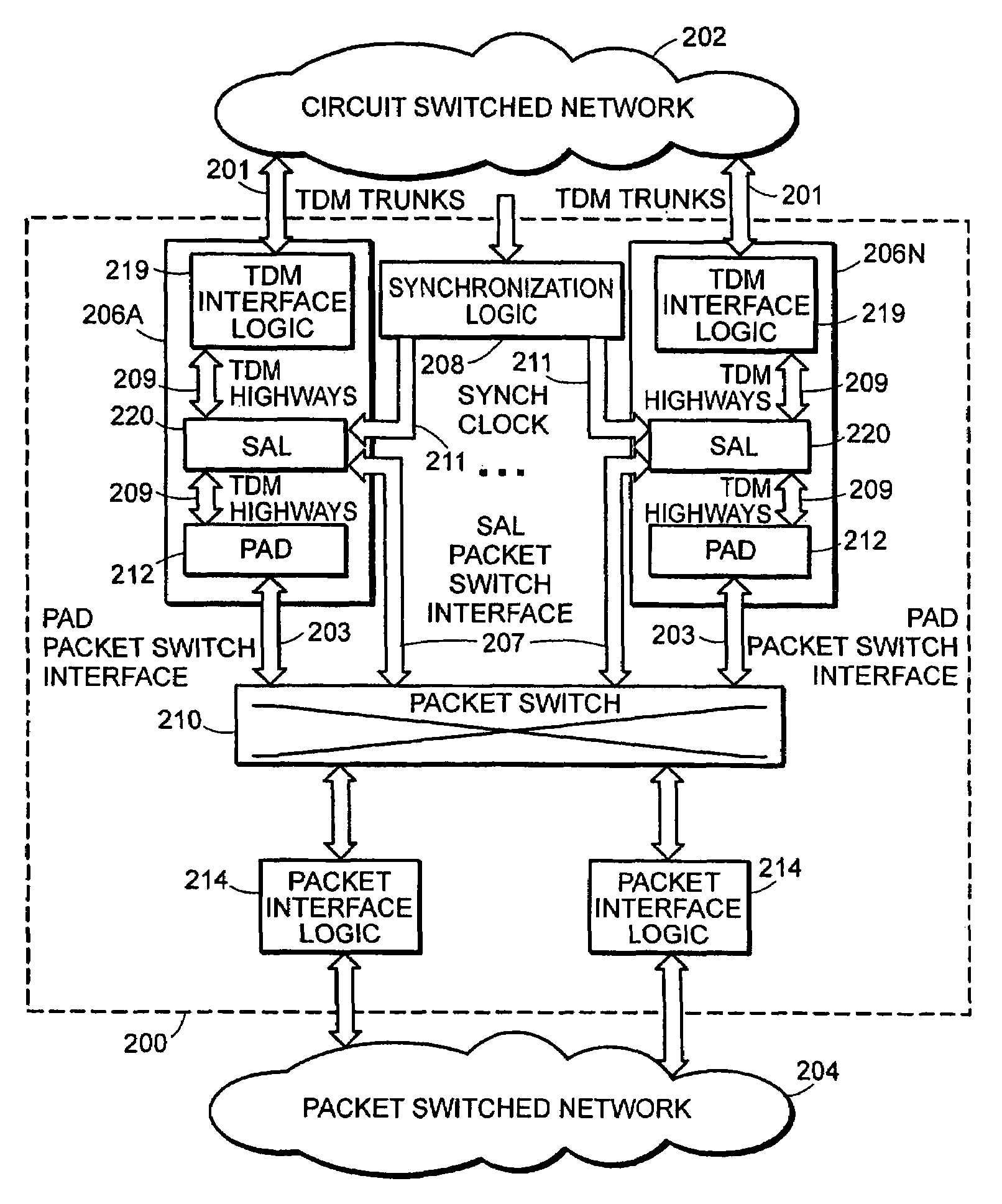
[0042]An apparatus in accordance with an illustrative embodiment of the present invention is illustrated in FIG. 3. Apparatus 200 interconnects circuit-switched network 202 and packet-switched network 204 and facilitates the transmission of data within the packet-switched and circuit-switched domains, as well as across such domains. Apparatus 200 comprises a plurality of network server modules 206A-N, synchronization logic 208 and an asynchronous switch 210. Apparatus 200 further comprises Packet interface logic 214 that interconnects asynchronous switch 210 to packet network 204.

[0043]Since synchronization is critical for controlling delay through the system and maintaining alignment of data from separate time slots, the synchronization logic 208 of apparatus 200 provides a special synchronization clock signal to all server modules 206A-N. Such synchronization clock signal is different from a network clock signal or the clock signal used by the asynchronous switch 210. In the illus...


PUM


Abstract

A gateway apparatus includes multiple network server cards which are synchronized with each other to allow time slot switching of synchronous data across an asynchronous medium between source and destination server cards. The gateway includes synchronization logic and a data adaptation layer which implements a protocol for formatting of synchronous serial data. The data undergoes serial to parallel conversion and is formed into per time slot subpackets which are further packetized along with context and synchronization data. The packet is transmitted through an asynchronous switch after which the packet is disassembled into its constituent subpackets and queued into play-out buffers according to each subpackets' associated context and synchronization data. The apparatus allows synchronous data to be switched from a source time slot to a destination time slot across the asynchronous switch with a known, fixed delay. The gateway apparatus requires only a single asynchronous switch to transmit data between and among both the synchronous and asynchronous domains.

Description

RELATED APPLICATIONS[0001]This application is one of two related applications filed on an even date herewith and commonly assigned, including U.S. patent application Ser. No. 10 / 685,053, entitled “METHOD AND APPARATUS FOR SYNCHRONIZED TRANSPORT OF DATA THROUGH AN ASYNCHRONOUS MEDIUM”, the subject matter of which is incorporated herein by reference for all purposes.FIELD OF THE INVENTION[0002]The invention relates, generally, to communications systems, and, more specifically, to a gateway apparatus which utilizes a single switch to route both synchronous and asynchronous data streams.BACKGROUND OF THE INVENTION[0003]Two fundamentally different switching technologies exist that enable telecommunications. First, circuit-switching technology utilizes dedicated lines or channels to transmit data between two points, similar to public switched telephone networks (PSTN). The second, packet switching technology, utilizes a “virtual” channel to establish communications between two points. The...

Claims


Application Information

Patent Timeline
Patent Type & Authority Patents(United States)
IPC IPC(8): H04L12/28H04B7/212H04J3/06
CPCH04J3/0685
Inventor SMITH, MARKLI, SHIPINGPASCO-ANDERSON, JAMES
Owner RIBBON COMM OPERATING CO INC
Why Eureka
Try Eureka