Free piston pressure spike modulator for any internal combustion engine

a technology of free piston and modulator, which is applied in the direction of machines/engines, reciprocating piston engines, positive displacement engines, etc., can solve the problems of serious damage to engines and air pollution, and achieve the effect of boosting engine output, avoiding sacrificing performance, and boosting turbochargers

Inactive Publication Date: 2009-09-15
H BRUCE CROWER & BARBARA M CROWER AS CO TRUSTEES UNDER THE CROWER FAMILY TRUST
View PDF1 Cites 11 Cited by
  • Summary
  • Abstract
  • Description
  • Claims
  • Application Information

AI Technical Summary

Benefits of technology

[0017]The free piston spike modulator and method of use on internal combustion engines herein described and disclosed may be employed to reduce the high pressure spike which occurs upon the ignition of fuel and oxidizer in the cylinder of a conventional internal combustion engine. Those skilled in the art will realized that such a peak or spike in pressure is conventionally graphically depicted in a Pressure / Volume (p / v) diagram. The device herein when engaged in a sealed communication with the upper end of an engine cylinder, absorbs and stores peak pressure and spreads the pressure increase in the engaged cylinder over a wider range, eliminating the need for heavy components such as reinforced pistons, heavy connecting rods, and strengthened crank-shafts and crankcases. The device when engaged thereto provides an “elastic” or virtual combustion chamber for gas expansion, without sacrificing performance. When in sealed engagement with engine cylinders, it will allow gasoline engines (such as aircraft requiring high octane fuel) to use diesel fuels, or “Jet A” (commonly available worldwide) in place of gasoline in engine structures of conventional gasoline design using conventionally employed lower weight components. The device and method will also allow higher turbo charging boosts in internal combustion engines using a boosted fuel and oxidizer intake, without exceeding ordinary gasoline cylinder pressures during combustion. This allows for higher boost of the engine output without the extra engine reinforcement normally required.
[0018]Still further, the device may be employed as a means to reduce greenhouse gases and air pollution by reducing the Nitrous Oxide formed during conventional cylinder high combustion pressures which conventionally cause more pollution in the atmosphere. When operatively engaged to any cylinder of an internal combustion engine, the device prevents formation of NOX through reduction of the peak cylinder pressures which cause NOX formation. Since Nitrous Oxide is reduced or does not form in the first place during the more even pressures of combustion, there is a resulting significant reduction of Nitrous Oxide in the engine exhaust communicated to the atmosphere. As both a means for fuel adaptation in the engine and a Nox reduction apparatus, the device herein disclosed may be retrofitted on existing engines or installed as a stock component in new engine manufacture.
[0020]Details such as the workings of a pressure regulator, fittings, and other items are not shown in order to simplify the general drawings of this invention. However, such components are well known to those skilled in the art to provide a pressurized environment to the high pressure chamber of a reciprocating piston thereby providing resistance to that piston of the device from translating. This effectively increases the venting chamber dimension under pressure from the engaged combustion chamber of the engine cylinder. The pressure in the high pressure chamber of the device provides both resistance and resulting pressure levels in the venting chamber and also a cushion zone preventing the piston of the device from impacting a back wall. Lubrication would also be provided to the device by conventional means such as communication with the engine pressurized oil conduits.

Problems solved by technology

However, in the extreme pressures produced in engines employed in racing conditions (such as tractor pulling contests), such engines are seriously damaged, regardless of the costly heavy duty components employed in the engine to accommodate the pressures anticipated.
Additionally, the high combustion pressures and temperatures in all internal combustion engines conventionally cause air pollution through generation of nitrous oxide created by the ignition process of the fuel and oxygen.

Method used


Image

  • Free piston pressure spike modulator for any internal combustion engine
  • Free piston pressure spike modulator for any internal combustion engine
  • Free piston pressure spike modulator for any internal combustion engine

Examples


Embodiment Construction

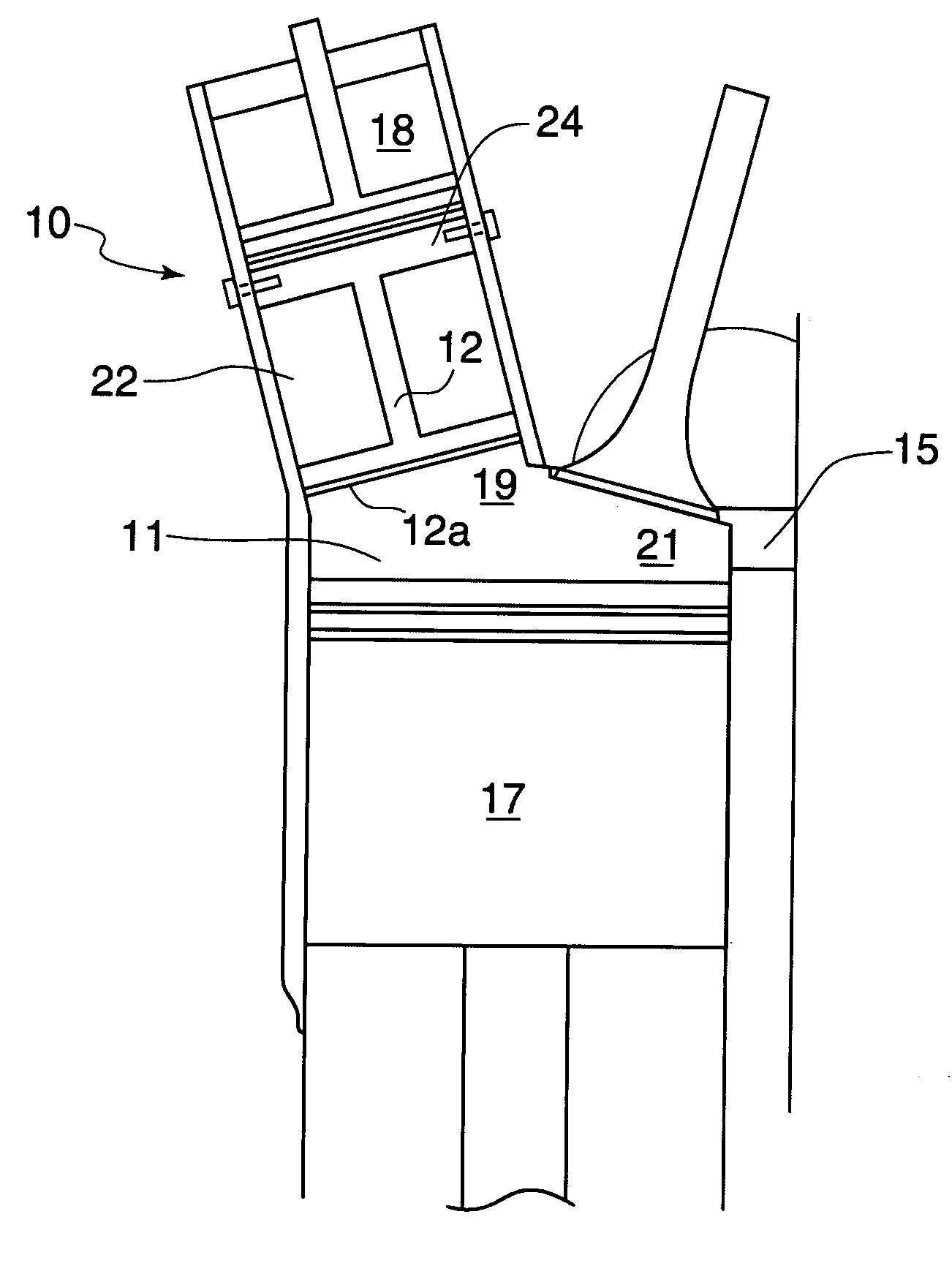
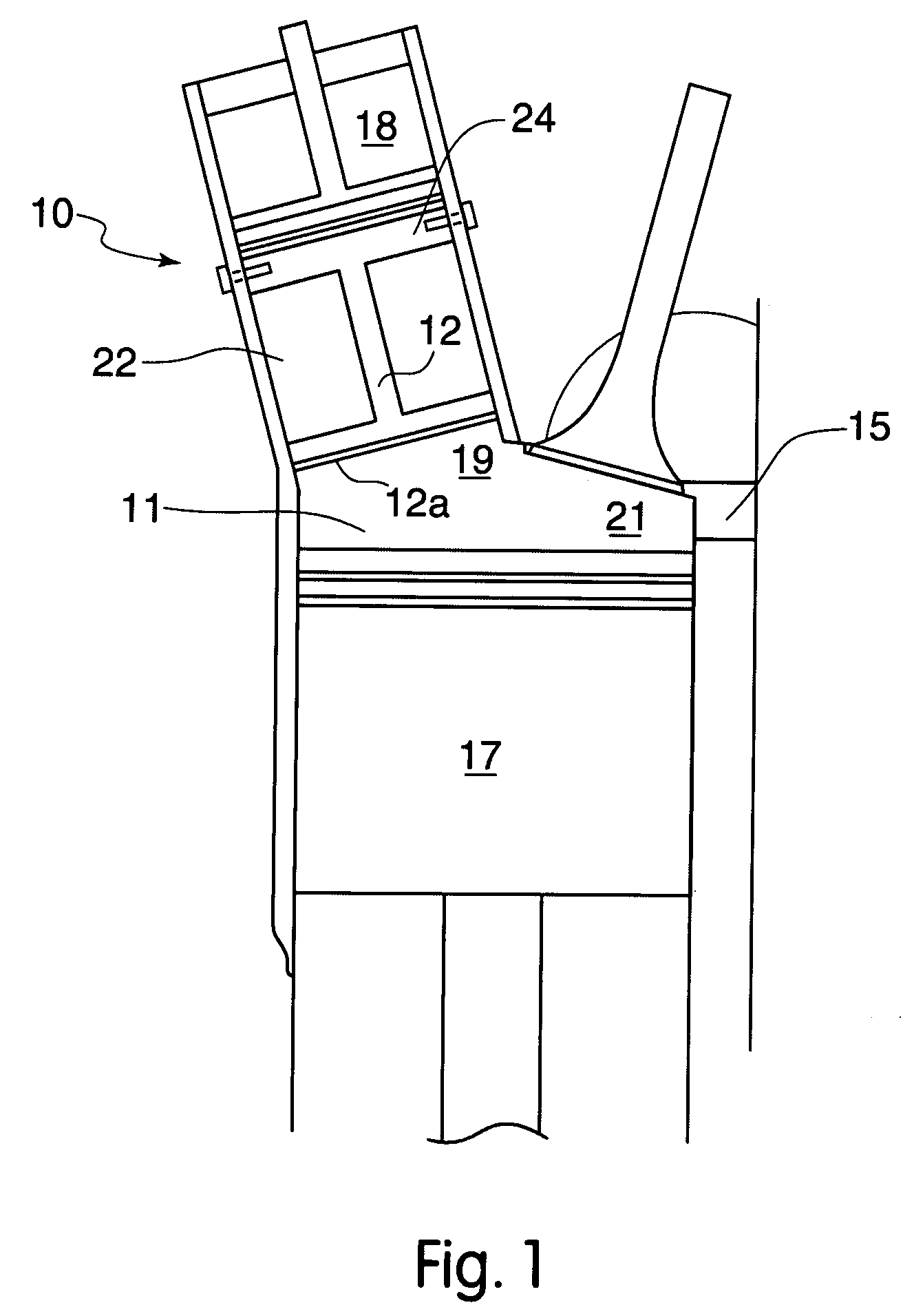
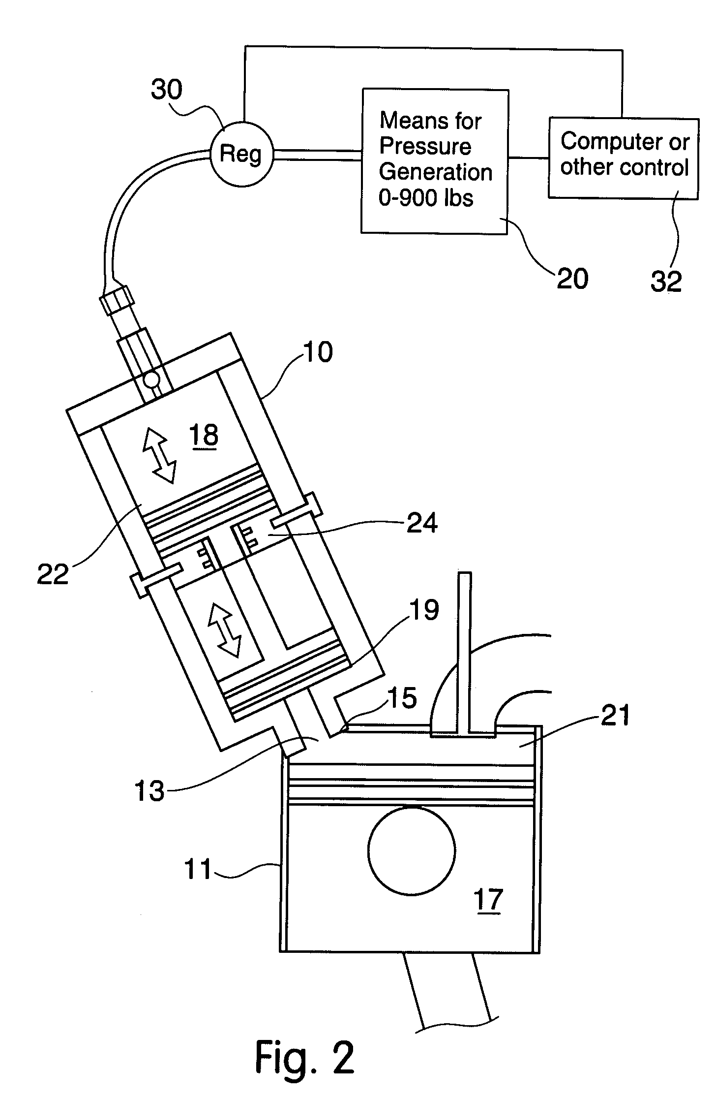
[0027]Referring now to the drawings in FIGS. 1-4, wherein similar parts are identified by like reference numerals, there is seen in FIG. 1, a mode of the device integral in design and as it might be incorporated in a new engine during manufacture. In FIG. 2 the device 10 as it might be employed as a retrofit engaged to the engine cylinder 11 through the spark plug aperture 13 in the cylinder head 15 is depicted. In all modes of the device 10 it will function to modulate the peak engine cylinder 11 pressure to which it is engaged by absorbing and storing cylinder pressure during portions of the engine cylinder stroke, and communicating that pressure back into the cylinder 11 of the engine during each stroke of the engine piston 17.

[0028]Combustion commences generally at a time when a lower wall 12a of the piston 12 of the device 10 is in a lower position. A biasing is provided by back pressure communicated to the upper wall 12b of the piston 12 in the upper chamber 18 of the device 1...


PUM


Abstract

A pressure spike modulator for engagement to the cylinders of an internal combustion engine. The device provides for adjustment of engine cylinder pressures using a reciprocating piston which provides a temporary increase in engine combustion chamber volume. Pressure from combustion chamber gases is communicated by the device back into the combustion chamber during the downstroke of the engine piston. Engine compression and peak combustion pressure may be modulated by adjusting pressure supplied to the device to resist incoming engine gases. Fuels for the attached engine may thereby be varied or substituted by adjusting the engine peak pressure and compression to one adequate for the chosen fuel.

Description

[0001]This application is a continuation-in-part to and claims the benefit of U.S. Provisional Application No. 60 / 842,498 filed Sep. 5, 2006 and incorporated herein in its entirety by reference.FIELD OF THE INVENTION[0002]The disclosed device relates to internal combustion engines. More particularly it relates to an apparatus and method engageable either during OEM manufacture or as a retrofit, which provides a secondary pressure chamber as a means to infinitely vary the compression ratio of a communicating engine cylinder and thereby concurrently vary the fuel required to run the engine. Further, the device and method provide a means to modulate the pressure spike occurring during cylinder combustion and particularly during combustion of diesel fuel in an internal combustion engine. Further, when engaged to a gasoline engine, the device and method herein will allow burning of diesel type fuels without reinforcement to the engine structure.BACKGROUND OF THE INVENTION[0003]Internal c...

Claims


Application Information

Patent Timeline
Patent Type & Authority Patents(United States)
IPC IPC(8): F02B75/04
CPCF02B75/042
Inventor CROWER, HARRY BRUCEMATHEWS, WILL W.
Owner H BRUCE CROWER & BARBARA M CROWER AS CO TRUSTEES UNDER THE CROWER FAMILY TRUST
Why Eureka
Try Eureka