Vapor analysis apparatus and method

a technology of vapor analysis and apparatus, applied in chemical methods analysis, chemical analysis using combustion, instruments, etc., can solve the problems of significant human error in the data collection process, cumbersome vapor analysis systems, and inefficient use of conventional vapor analysis systems by workers, so as to improve ease-of-use and system operation.

Active Publication Date: 2009-09-15
CISCO TECH INC +1
View PDF38 Cites 47 Cited by
  • Summary
  • Abstract
  • Description
  • Claims
  • Application Information

AI Technical Summary

Benefits of technology

[0026]Certain embodiments of the system also include a handheld data entry device such as a keypad that is in communication with the controller in the system housing. The keypad provides additional unique capabilities that further enhance ease-of-use and system operation.
[0027]In operation, the control program causes the controller to operate the vapor analyzer in a monitoring or survey mode to continually collect and monitor the vapor sample for detection of one or more compounds that may be contained within the vapor sample. The control program can also cause the controller to modulate the indicator signal to control an operation of the user indicator, such as a light or speaker on or in the sample probe. Modulation is relative to the concentration of the compound detected by the vapor analyzer within the vapor sample such that a detected increase in concentration of the compound may for example, cause the controller to increase modulation of the indicator signal sent to the user indicator. The control program can also cause the controller to provide a predetermined threshold indicator signal modulation pattern when the vapor analyzer detects a threshold concentration of the compound that exceeds a predetermined value. Thus the user of the sample probe can, while holding the probe in almost any position, determine (e.g., visually, by simply viewing the multi-dimensional user indicator, or audibly if the user indicator produces sound) that the vapor analyzer has detected the threshold concentration of the compound. The user indicator may flash or beep according to a predetermined threshold indicator signal modulation pattern, so the user can quickly identify leaking equipment in the vicinity of the leak point. There may be a minimum threshold level where the system does not increase the modulation of the indicator signal if a detected vapor concentration is below a specified value.

Problems solved by technology

Conventional systems, mechanisms and techniques for performing analysis of compounds that may be contained within vapor samples such as those used in fugitive emissions monitoring programs suffer from a variety of deficiencies.
In particular, conventional vapor analysis systems are cumbersome and inefficient to use by workers in the field when performing vapor analysis and leak detection activities for numerous leak points defined in a long route list.
Such non-integrated systems allow significant opportunity for human error in this data collection process.
However, such conventional integrated vapor analysis systems that can receive route list information and that can then associate a detected concentration of a compound to a particular route list entry (i.e., leak point) within the route list without manual data entry still suffer from a variety of operational and design constraints that limit their efficiency in practice.
Accordingly, since the embedded software within the conventional TVA-1000 system uses a fixed data format, it is difficult if not impossible for a typical user or operator to make modifications to the fugitive emissions application software database format that operates in the stationary computer system.

Method used


Image

  • Vapor analysis apparatus and method
  • Vapor analysis apparatus and method
  • Vapor analysis apparatus and method

Examples


Embodiment Construction

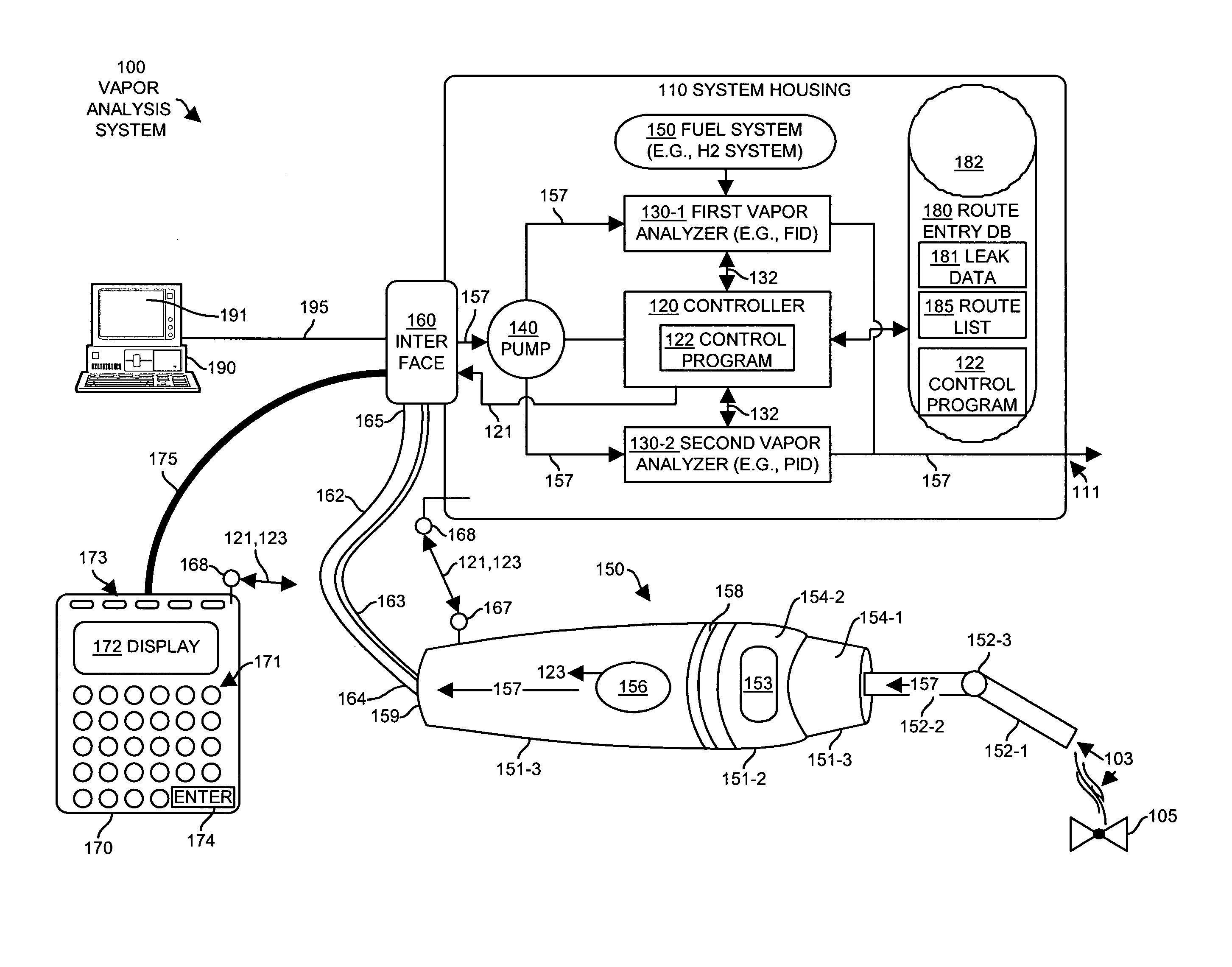
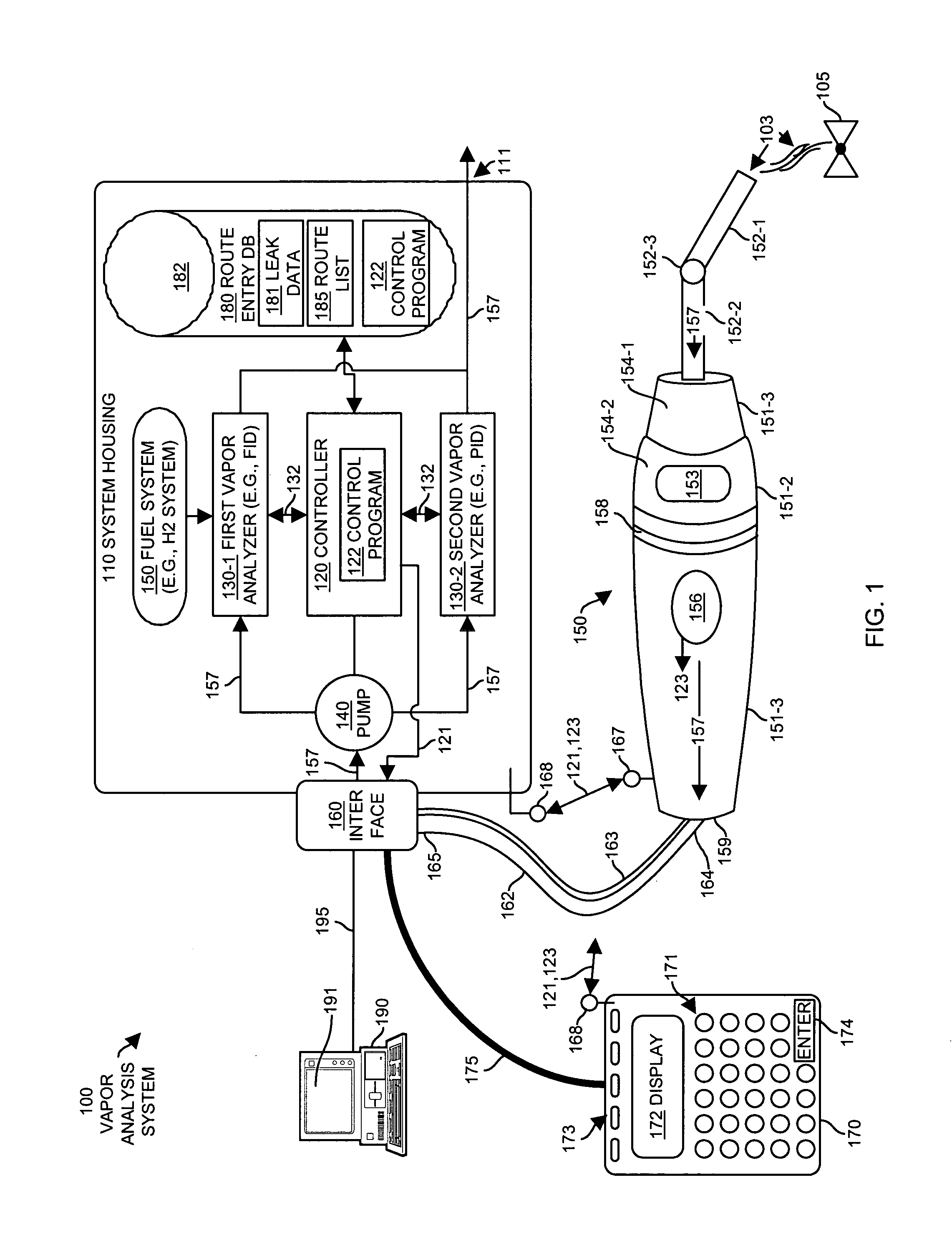
[0040]FIG. 1 illustrates a vapor analysis system 100 configured according to one example embodiment of the invention. The example vapor analysis system 100 includes a sample probe 150 and a keypad 170 coupled via an interface 160 to a system housing 110. The system housing is portable and may be placed, for example, in a backpack or a person may wear it as an attachment to a belt so as to allow the person to move freely in the field during monitoring operations. The backpack can include a belt portion containing a holster, clip, snap or other attachment mechanism for the keypad 170 and the probed 150 for holding those items when note in use. A stationary computer system 190 operating a vapor analysis software management program 191 couples via a data communications link 195 to the interface 160 of the system housing 110. Generally, the stationary computer system 190 is not considered part of the vapor analysis system 100 during field operation of the system housing 110, the keypad 1...


PUM

PropertyMeasurementUnit
timeaaaaaaaaaa
concentrationaaaaaaaaaa
threshold concentrationaaaaaaaaaa

Abstract

A vapor analysis system comprising a vapor analyzer capable of collecting and analyzing a vapor sample for detection of a compound that may be contained within the vapor sample. A controller is coupled to the vapor analyzer. The controller is programmed to produce an indicator signal indicative of a relative concentration of the compound detected by the vapor analyzer within the vapor sample. A sample probe includes a housing containing a vapor channel through which the vapor sample is collected, and a vapor cable couples the sample probe to the vapor analyzer to allow collection and channeling of the vapor sample to the vapor analyzer. A multi-dimensional user indicator is disposed on the housing of the sample probe receives and operates in response to the indicator signal to indicate the relative concentration of the compound detected within the vapor sample for presentation via a multi-directional stimulus to a user of the vapor analysis system. Users are able to create user-defined fields in a route entry database and are able to edit route entries while using the vapor analysis system in the field.

Description

FIELD OF THE INVENTION[0001]The present invention generally relates to systems that detect the presence of compounds contained within air or other gas samples and more particularly, to systems that operate as portable gas or vapor measurement systems.BACKGROUND OF THE INVENTION[0002]Vapor analysis monitoring is an activity that involves detecting and measuring compounds that may be contained within vapor or gas samples collected from a certain region or volume of space. Vapor analysis monitoring is sometimes called “fugitive emissions monitoring” (FEM) and people often use conventional portable vapor analysis monitoring systems as a mechanism to routinely detect chemical leaks from industrial processing equipment such as valves, pipes, flanges, machinery, instrumentation or other equipment installed within industrial facilities such as petroleum refineries, chemical plants, pharmaceutical production facilities, pulp and paper processing facilities and the like. In some of these indu...

Claims


Application Information

Patent Timeline
Patent Type & Authority Patents(United States)
IPC IPC(8): G01N1/22G01N21/00G01N27/00G01N30/00
CPCG01N1/2205G01N35/00871G01N33/0009G01N27/626Y10T436/25875
Inventor MOURADIAN, ROBERT F.KENNEDY, PATRICK JOHNJOHNSON, JR., K. STEPHEN
Owner CISCO TECH INC
Why Eureka
Try Eureka