Circuitry and method for detecting and protecting against over-clocking attacks

Active Publication Date: 2009-09-15
NAT SEMICON CORP
View PDF6 Cites 51 Cited by
  • Summary
  • Abstract
  • Description
  • Claims
  • Application Information

AI Technical Summary

Benefits of technology

[0026]It therefore is an object of the present invention to provide hardware means for detecting, and protecting against, over-clocking attacks on hardware modules. It is another object to provide hardware means which can be embedded into digital circuitry cells of an integrated circuit, for detecting, and protecting against, over-clocking attacks on hardware modules. It is a further object to provide hardware means, for efficient and fast detection of over-clocking attacks of hardware modules, without utilizing dedicated sensors for indicating deviation of each element in the operating condition (e.

Problems solved by technology

However, the wide acceptance of these devices has made the security schemes utilized by them more vulnerable to tampering and hacking attempts, which jeopardize the secret data and authenticity of transactions.
However, these types of attacks that do not involve tampering with the hardware device are rather complex and do not guarantee successful results.
Another type of attack is fault-based cryptanalysis, which often involves direct physical attack of the hardware including the security module.
Typically, the errors are induced in such attacks by altering the power supply voltage/current, operating temperature, and/or the clock frequency of the security module, and/or by applying magnetic or electromagnetic radiation.
Some of the common errors caused during fault-based cryptanalysis attacks are due to disruptions in the functionality of the device's synchronous (i.e., clock driven) modules, such as the CPU (Central Processing Unit).
These disruptions are typically caused by violating the module's operating conditions requirements.
Generally, paths having longer delay times are more likely to fail under such attacks.
As a result of such attacks, execution of the wrong instructions can be carried out, the resul

Method used


Image

  • Circuitry and method for detecting and protecting against over-clocking attacks
  • Circuitry and method for detecting and protecting against over-clocking attacks
  • Circuitry and method for detecting and protecting against over-clocking attacks

Examples


Embodiment Construction

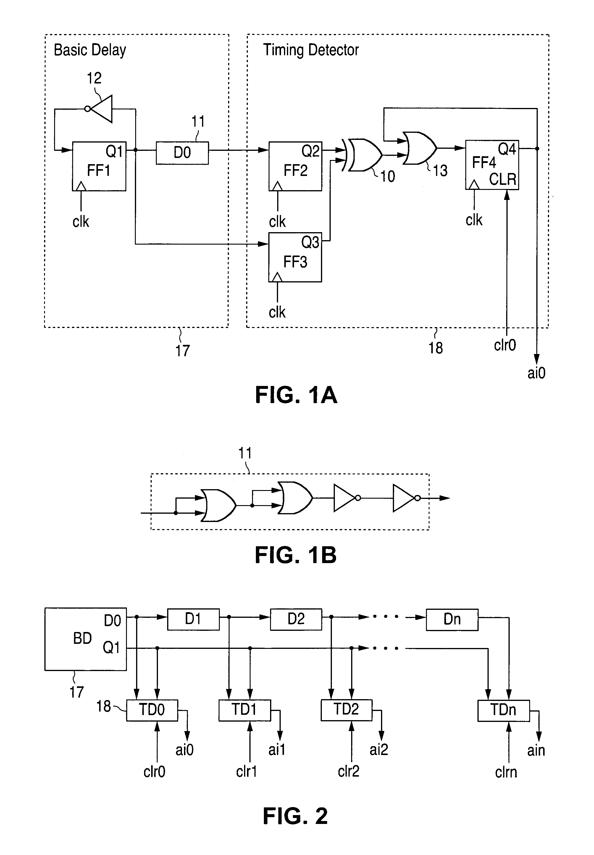
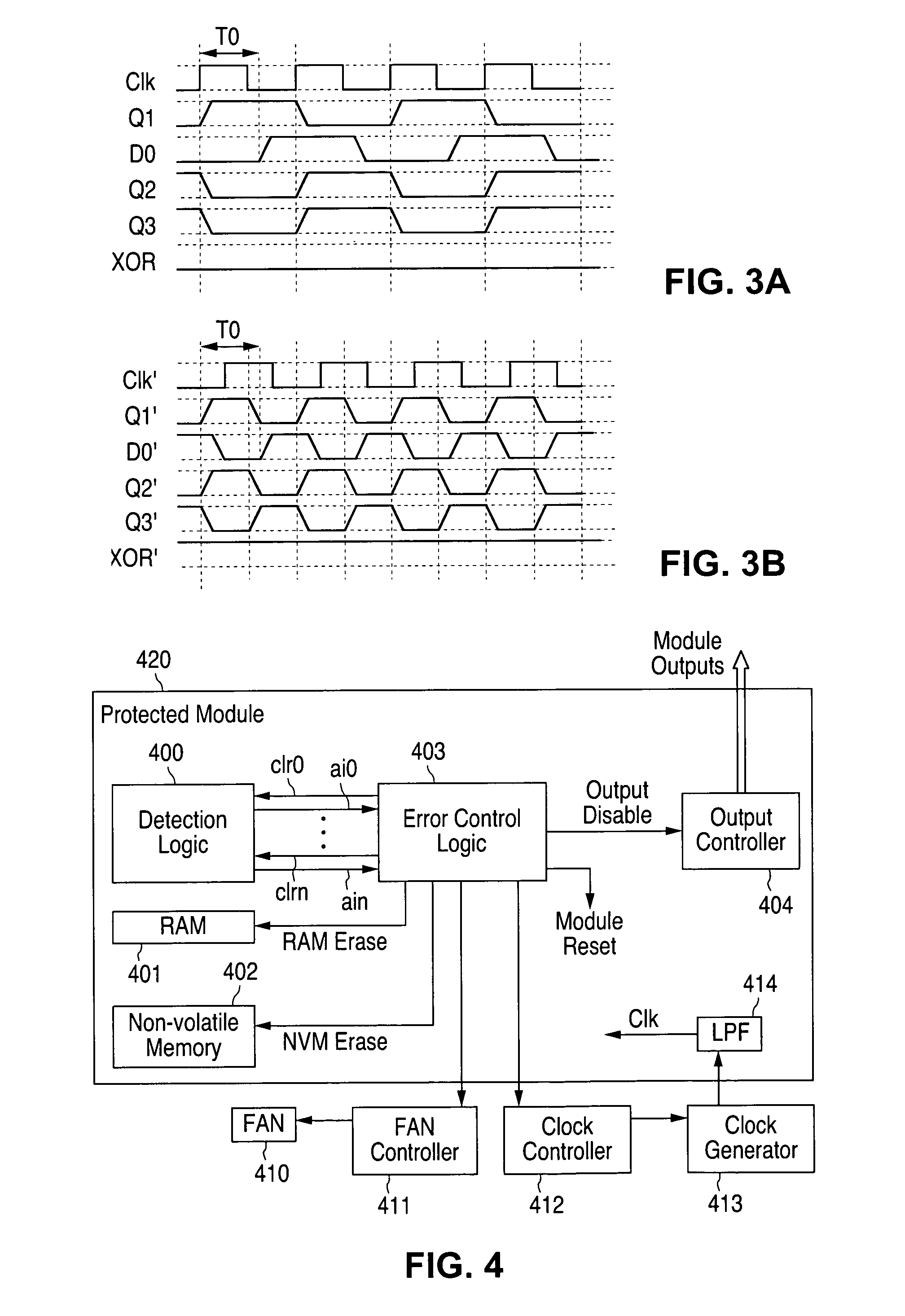
[0017]FIGS. 1A through 4, discussed below, and the various embodiments used to describe the principles of the present invention in this patent document are by way of illustration only and should not be construed in any way to limit the scope of the invention. Those skilled in the art will understand that the principles of the present invention may be associated with any suitably arranged cryptographic modules wherein protection against over-clocking (e.g., frequency, voltage and heat) attacks is desired.

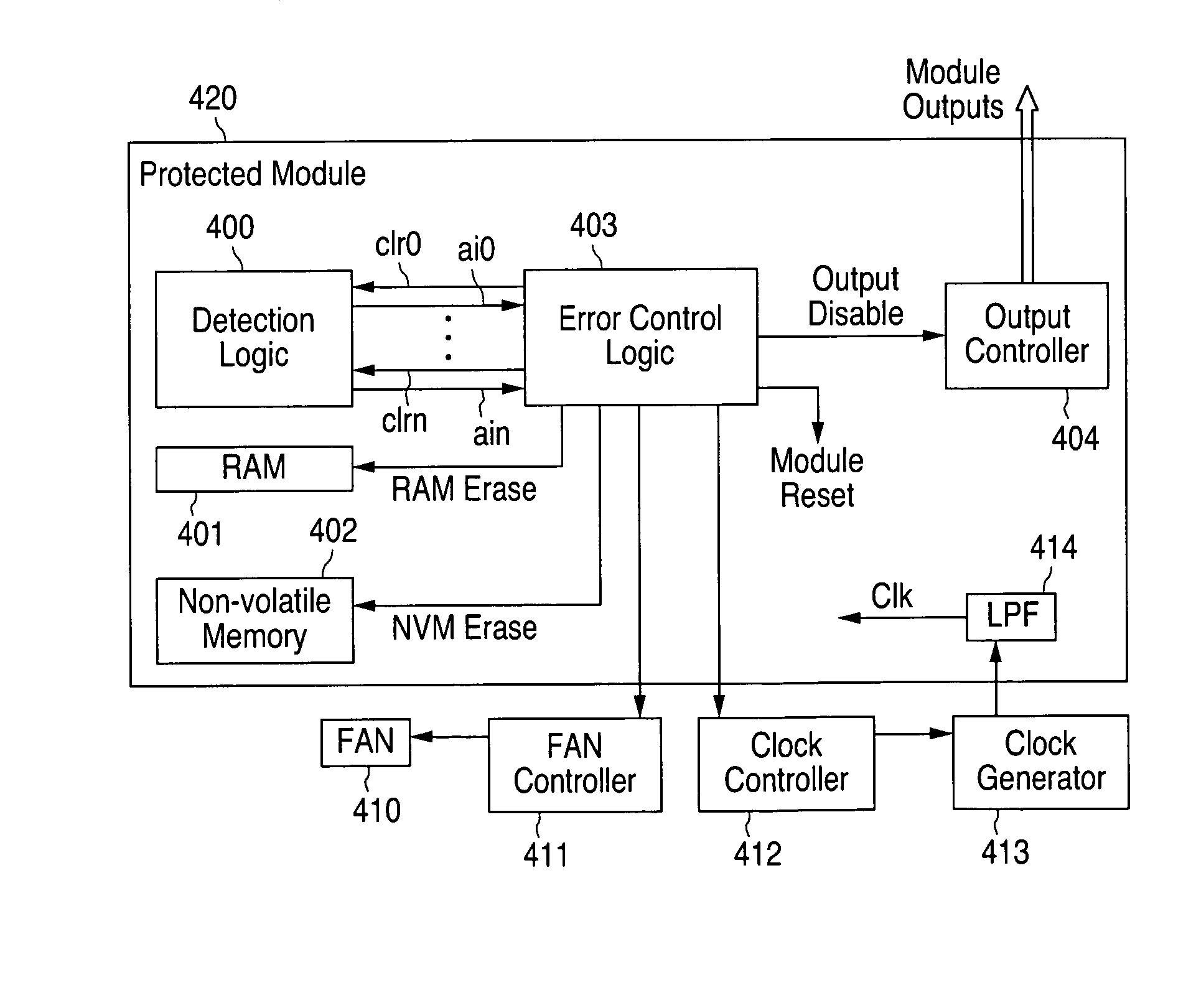
[0018]To address the above-discussed deficiencies of the prior art, the present invention is directed to circuitry for detecting and protecting against over-clocking attacks on a hardware module. More particularly, the circuitry of the invention aims to protect against attacks attempting to induce timing violations, such as clock attacks (e.g., increasing clock frequency), heat attacks (e.g., warming the protected module), and voltage attacks (e.g., lowering its supply voltage), whic...


PUM


Abstract

The present invention is directed to circuitry for detecting and protecting against over-clocking attacks on hardware modules. The circuitry preferably comprises a test signal, a delay path for providing a delayed signal of the test signal, and circuitry for comparing the logical state of the test signal and the delayed signal and issuing an attack indication whenever the signals are different.

Description

TECHNICAL FIELD OF THE INVENTION[0001]The present invention relates to the detection of, and the protection against, fault-based attacks on hardware modules such as cryptanalysis attacks and other attacks on data shielded within the hardware module. More particularly, the invention relates to a circuitry that provides protection against over-clocking (e.g., frequency, voltage and heat) attacks on cryptographic modules.BACKGROUND OF THE INVENTION[0002]The demand for increased security of electronic transactions is rapidly increasing due to the vast number of devices which are now adapted for communicating over data networks. Typically, a security module (e.g., TPM—Trusted Platform Module) employing cryptographic schemes is embedded into such applications (e.g., PC computers). for managing secret data and for protecting user's privacy. However, the wide acceptance of these devices has made the security schemes utilized by them more vulnerable to tampering and hacking attempts, which j...

Claims


Application Information

Patent Timeline
IPC IPC(8): G06F1/04
CPCG06F21/558G06F21/755
Inventor HERSHMAN, ZIV
Owner NAT SEMICON CORP
Why Eureka
Try Eureka