Perpendicular magnetic recording medium

a magnetic recording medium and perpendicular technology, applied in the field of perpendicular magnetic recording medium, can solve the problems of increasing noise, increasing orientation dispersion, increasing signal output, etc., and achieves the effects of promoting magnetic isolation of magnetic crystal grains in the magnetic recording layer, reducing medium noise, and improving s/n

Active Publication Date: 2009-09-22
FUJI ELECTRIC CO LTD
View PDF17 Cites 6 Cited by
  • Summary
  • Abstract
  • Description
  • Claims
  • Application Information

AI Technical Summary

Benefits of technology

[0015]In light of these circumstances, as the result of assiduous researches by the inventors, it was discovered that, by sequential layering of a first underlayer, a first nonmagnetic intermediate layer, a second underlayer, and a second nonmagnetic intermediate layer, by dividing the nonmagnetic intermediate layer into two layers, and by using as the first and second underlayer materials a soft magnetic material having a face-centered cubic (fcc) structure, the film thickness of the second nonmagnetic intermediate layer could be reduced to 0.1-20 nm to secure a sharp recording material field. The medium performance could simultaneously be improved in such respects as reduced noise, improved S / N, and improved write-ability of the perpendicular magnetic recording medium, culminating in the completion of this invention.
[0020]By adopting the above-described configuration, the film thickness of the second nonmagnetic intermediate layer is reduced to between 0.1 nm and 20 nm, the orientation dispersion and crystal grain diameters in the magnetic recording layer are reduced, and magnetic isolation of magnetic crystal grains in the magnetic recording layer can be promoted. As a result, reduction of medium noise and improvement of the S / N, and improvement of write-ability through reduction of the distance between the soft magnetic film and magnetic head, can be achieved simultaneously. Further, by reducing the thickness of the nonmagnetic intermediate layer, costs can simultaneously be lowered.

Problems solved by technology

One cause of a decrease in signal output and an increase in noise is an increase in orientation dispersion (crystal orientation irregularity) in the magnetic recording layer.
If there is large dispersion in the orientation of this easy axis of magnetization, then the consequent reduction in the perpendicular-direction flux causes a decline in signal output.
If the crystal grain diameters in the magnetic recording layer are large, then bit transition regions become irregular, and transition noise increases.
Such a thick underlayer or intermediate layer is inadequate for shortening the distance between the magnetic head and the soft magnetic backing layer and obtaining a high S / N in high-density recording.
However, when the film thickness of the underlayer or intermediate layer is reduced, not only a lessening of the crystal orientation of the magnetic recording layer material, but also impediments to the magnetic isolation between magnetic crystal grains occur.

Method used


Image

  • Perpendicular magnetic recording medium
  • Perpendicular magnetic recording medium
  • Perpendicular magnetic recording medium

Examples


embodiments

Embodiment 1

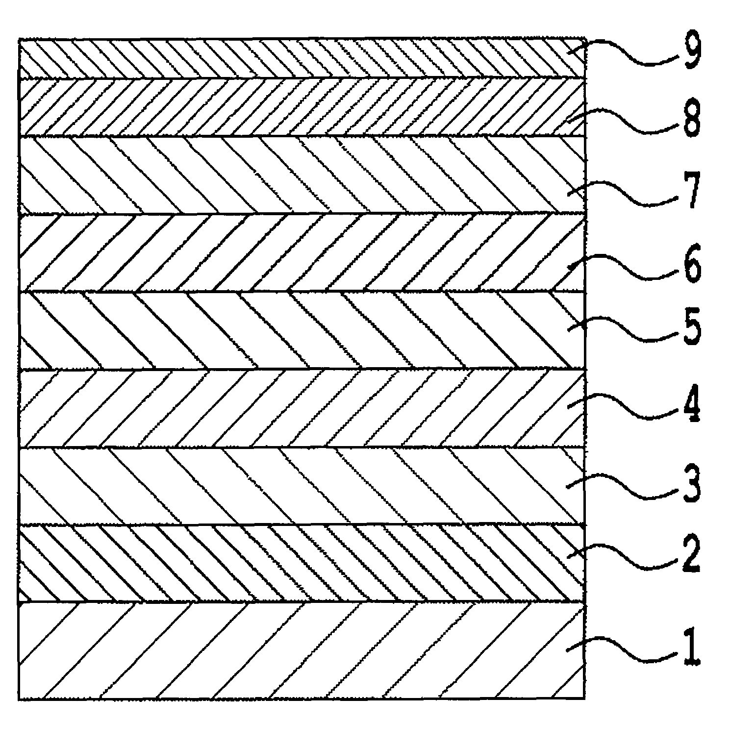
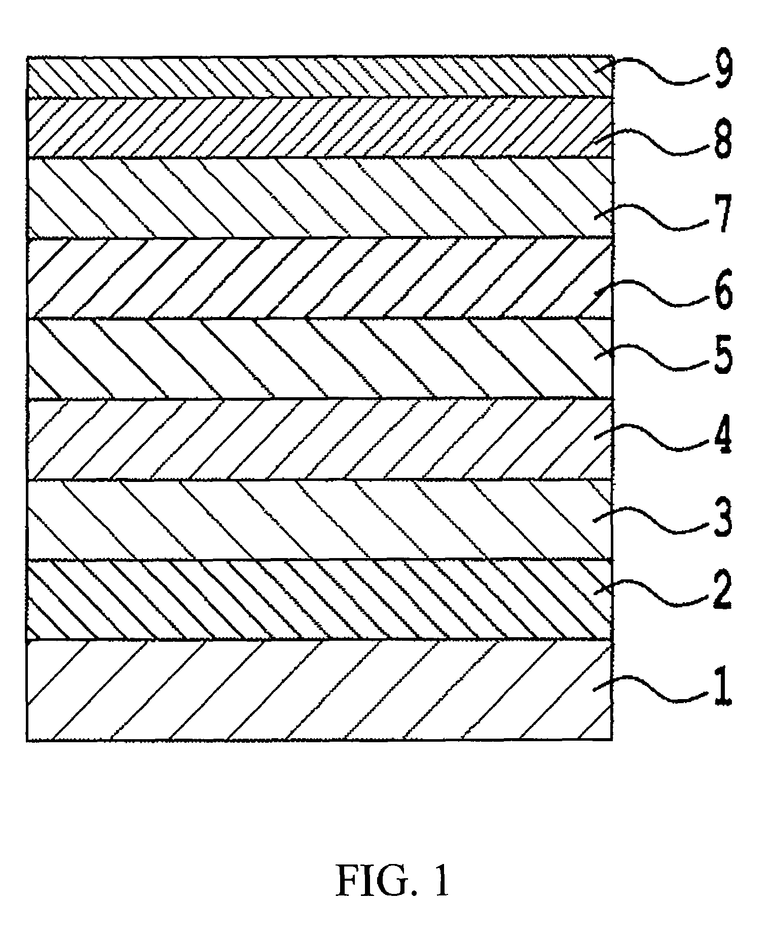
[0043]As the nonmagnetic substrate 1, a chemically reinforced glass substrate with a smooth surface (N-5 glass substrate manufactured by HOYA Corporation) was used; after cleaning, the substrate was placed in a DC magnetron sputtering system, and a Co3Zr5Nb target (taking as reference the total number of atoms, 3 at % Zr, 5 at % Nb, remainder Co; similarly hereafter) was used in an Ar gas atmosphere at a pressure of 0.67 Pa to deposit a CoZrNb amorphous soft magnetic backing layer 2 of film thickness 60 nm. Next, a Co35Ni4Fe2Si target was used in an Ar gas atmosphere at 0.67 Pa to deposit a CoNiFeSi first underlayer 3 of film thickness 6 nm. The CoNiFeSi film obtained has the fcc structure. Next, a Ru target was used in an Ar gas atmosphere at a pressure of 0.67 Pa to deposit a Ru first nonmagnetic intermediate layer 4 of thickness 0.7 nm. Then, in an Ar-4% N2 gas atmosphere at pressure 0.67 Pa, a Co4Fe target was used to deposit a CoFe—N second underlayer 5 of thickness...

embodiment 2

[0044]Except for using a Ni12Fe4Si target to deposit an NiFeSi first underlayer 3 of thickness 6 nm, the same method as in Embodiment 1 was repeated to manufacture the perpendicular magnetic recording medium. Here, the NiFeSi film obtained had the fcc structure.

embodiment 3

[0045]Except for using a Ru target to deposit a Ru first nonmagnetic intermediate layer 4 of thickness 1.6 nm, the same method as in Embodiment 1 was repeated to manufacture the perpendicular magnetic recording medium.


PUM

PropertyMeasurementUnit
thicknessaaaaaaaaaa
thicknessaaaaaaaaaa
thicknessaaaaaaaaaa

Abstract

A perpendicular magnetic recording medium includes a nonmagnetic substrate; a first underlayer provided on the nonmagnetic substrate; a first nonmagnetic intermediate layer provided on the first underlayer; a second underlayer provided on the first nonmagnetic intermediate layer; a second nonmagnetic intermediate layer provided on the second underlayer; and a magnetic recording layer provided on the second nonmagnetic intermediate layer, wherein the first underlayer comprises a soft magnetic material which has a face-centered cubic structure and which includes at least Ni and Fe, and wherein the second underlayer comprises a soft magnetic material which has a face-centered cubic structure and which includes at least Co. The orientation dispersion is reduced and crystal grain diameters are smaller in the magnetic recording layer, and the film thickness of nonmagnetic intermediate layers can be decreased so that performance improvements such as reduced noise, increased S / N ratio, and improved write-ability are achieved.

Description

BACKGROUND OF THE INVENTION[0001]1. Field of the Invention[0002]This invention relates to a perpendicular magnetic recording medium mounted in various magnetic recording devices. More specifically, this invention relates to a perpendicular magnetic recording medium mounted in a hard disk drive (HDD) used as an external storage device of a computer, audio-video equipment, and similar.[0003]2. Description of the Related Art[0004]From 1997 on, there has been a rapid increase, at an annual pace of from 60 to 100%, in HDD recording densities. As a result of such remarkable growth, it is thought that the in-plane recording method that has been used in the past is approaching the limit of high-density recording. Given such circumstances, in recent years there has been much interest in perpendicular recording methods enabling higher recording densities, which has been the subject of much active research and development. And from 2005, at long last, HDDs adopting perpendicular recording meth...

Claims


Application Information

Patent Timeline
Patent Type & Authority Patents(United States)
IPC IPC(8): G11B5/66
CPCG11B5/7325G11B5/667G11B5/7368
Inventor TAKENOIRI, SHUNJISAKAI, YASUSHI
Owner FUJI ELECTRIC CO LTD
Why Eureka
Try Eureka