Fuel cell and electric apparatus

a technology of fuel cell and electric equipment, applied in the direction of fuel cells, regenerative fuel cells, cell components, etc., can solve the problems of increasing power consumption, difficult to provide a primary battery that can supply sufficient energy, and difficult to use a secondary battery at once at any time and in any location

Inactive Publication Date: 2009-09-22
CANON KK
View PDF10 Cites 3 Cited by
  • Summary
  • Abstract
  • Description
  • Claims
  • Application Information

AI Technical Summary

Benefits of technology

[0013]That is, in order to humidify an ionic conductor, it is an object of the present invention to provide a novel fuel cell system that can directly humidify a polymer electrolyte membrane using a simplified system that does not employ an apparatus such as a pump that serves to moisten a fuel in the above-described methods. It is also an object of the present invention to provide a fuel cell system that can eliminate water generated in an oxidizer electrode without using an apparatus such as a pump, and to provide an electric equipment that uses these fuel cell systems.

Problems solved by technology

However, due to recent improvements in performance of such equipment, power consumption has become greater, making it difficult to provide a primary battery that can supply sufficient energy while being compact and lightweight.
Further, recharging a secondary battery requires a separate power source and generally takes several tens of minutes to several hours, so that it is difficult to use a secondary battery at once at any time and in any location.
Although it is expected that in the future the electric equipment will become even smaller and lighter and the wireless network environment is being developed, increasing the tendency of using portable equipment, it will be difficult for conventional primary and secondary batteries to supply sufficient energy for driving equipment.
However, the ionic conductivity, which determines the performance of a polymer electrolyte fuel cell system, is greatly affected by the wettability of the polymer electrolyte membrane.
In particular, the conductivity dramatically drops due to drying of the polymer electrolyte membrane, so that an increase in the internal resistance will considerably degrade the characteristics of the fuel cell system.
However, in fuel cell system constructions such as described above, when the fuel cell system is large, methods that are used to humidify the fuel gas with water produced during power generation require a pump for transporting the generated water, because the fuel cell is distant from the fuel supply unit.
When a pump is used, power has to be supplied to the fuel cell system, so that such a system has the disadvantages of being larger and more complex.
Even for small fuel cell systems, when water generated in an oxidizer electrode is supplied to a fuel passage on a fuel electrode side, it is difficult to prevent the oxidizer from mixing with the fuel.
Because an oxidizer passage at the oxidizer electrode is narrow, unless the generated water is removed the passage is closed off by water droplets, whereby the oxidizer cannot be efficiently led to the oxidizer electrode.
However, in these methods it was difficult to quickly remove water generated in an oxidizer electrode.
These methods also suffered from the problem that when an attempt was made to lead the generated water in a certain direction, an apparatus using an electric power such as a pump or blower was required, thus enlarging the system.
For this reason, it was also difficult to store the used water in a given place.

Method used


Image

  • Fuel cell and electric apparatus
  • Fuel cell and electric apparatus
  • Fuel cell and electric apparatus

Examples


first embodiment

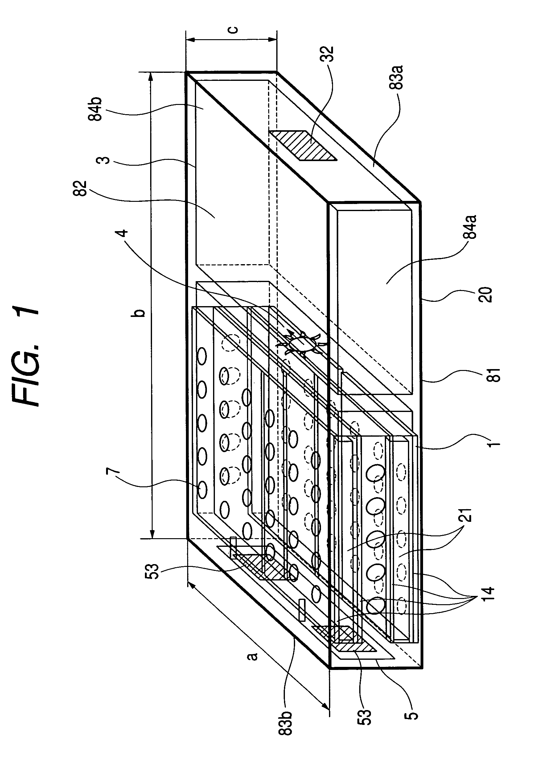
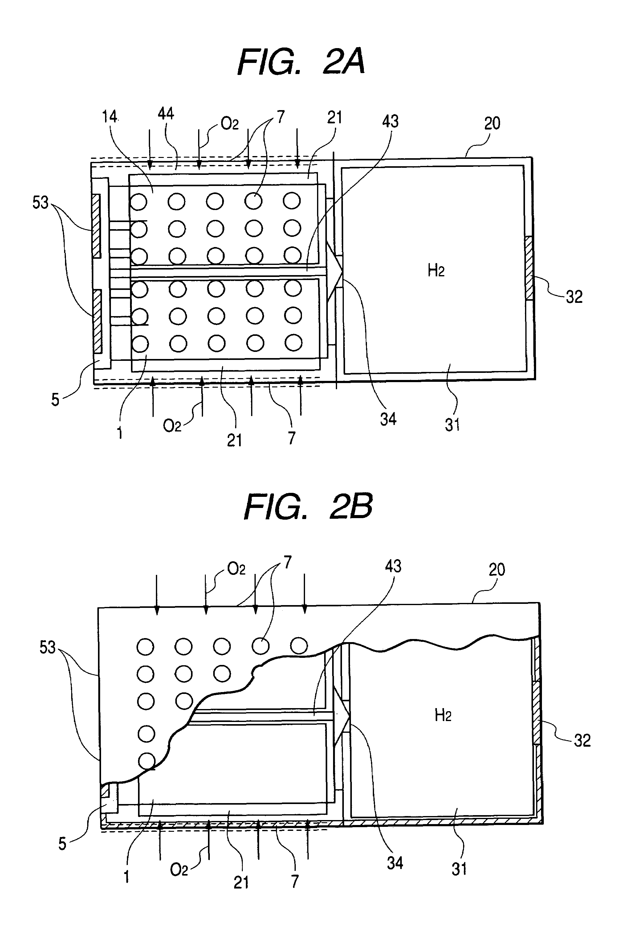
[0064]A fuel cell system according to a first embodiment of the present invention does not humidify a fuel, but has a humidifying means for directly humidifying a polymer electrolyte membrane.

[0065]FIG. 6 is a schematic cross-sectional view of a cell unit that comprises a humidifying means. As shown in FIG. 6, the present invention is characterized in that as the humidifying means 2a, a water holding unit 21 comprised of a water-absorbing material is provided at a position in contact with a polymer electrolyte membrane serving as an ionic conductor to directly humidify the polymer electrolyte membrane 12 serving as the ionic conductor utilizing an capillary action using water stored in the water holding unit, and more preferably that in order to moisten the polymer electrolyte membrane more rapidly and more uniformly, a humidification water passage 28 comprised of a hydrophilic material and connected to the water holding unit is provided in the polymer electrolyte membrane. Incident...

second embodiment

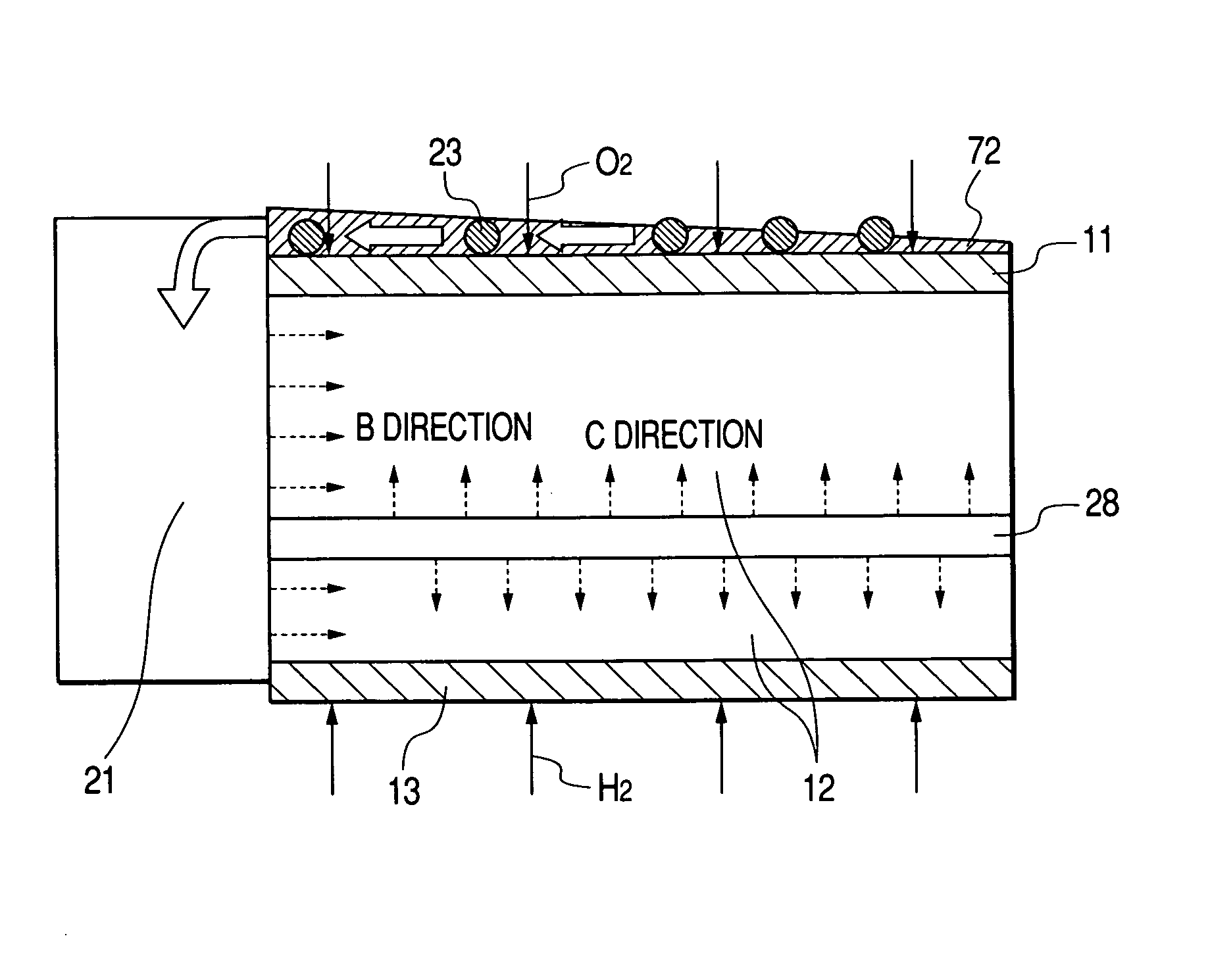
[0069]A fuel cell system according to a second embodiment of the present invention is characterized by having a water-moving pattern comprising a hydrophobic region and a hydrophilic region on a surface of an oxidizer electrode and water generated in the oxidizer electrode is moved by the water-moving pattern to be eliminated.

[0070]FIG. 6 is a schematic cross-sectional view of a cell unit having a humidifying means; FIG. 7 is a schematic view showing a water-moving pattern provided on a surface of an oxidizer electrode; and FIG. 9 is a schematic cross-sectional view showing one example of a water holding unit that stores water generated in a surface of an oxidizer electrode. That is, as shown in FIGS. 6, 7 and 9, in the present invention, by forming on a surface of an oxidizer electrode 11, a water-moving pattern 22 (water-moving means) comprised of a hydrophobic region 24 and a hydrophilic region 25 so that water moves in one direction, water 23 generated on the surface of the oxid...

third embodiment

[0072]A fuel cell system according to a third embodiment of the present invention will be explained in the following. The third embodiment is characterized in that as a water-moving means in place of the water-moving pattern of the second embodiment, a porous layer is provided on a surface of an oxidizer electrode of a cell unit in which the pore (hole) diameter of the porous material gradually becomes smaller in the water discharging direction, and the number of pores per unit volume (i.e. density) of the porous material gradually becomes greater in that direction. Such a porous layer allows the water generated in the oxidizer electrode to be removed.

[0073]FIG. 10 is a plan view of a cell unit having on the surface of an oxidizer electrode 11, a porous layer 71 in which the pore diameter of the porous material gradually becomes smaller in the A-direction. FIG. 11A is a cross-sectional view taken along line 11A-11A of FIG. 10. FIG. 11B is a schematic cross-sectional view of the poro...


PUM

PropertyMeasurementUnit
heightaaaaaaaaaa
widthaaaaaaaaaa
lengthaaaaaaaaaa

Abstract

A fuel cell system is provided which has a humidifying means (2) for directly humidifying a polymer electrolyte membrane (12) that serves as an ionic conductor. As the humidifying means (2), means is employed which has a water holding unit (21) comprised of a water-absorbing material and located in contact with the polymer electrolyte membrane to directly humidify the polymer electrolyte membrane (12) by utilizing a capillary action and further has a humidification water passage (28) comprised of a hydrophilic material and provided in the polymer electrolyte membrane so as to be connected to the water holding unit (21) to humidify the polymer electrolyte membrane (12) rapidly and uniformly. Such a constitution provides a fuel cell system that can directly humidify an ionic conductor.

Description

TECHNICAL FIELD[0001]The present invention relates to a fuel cell system and an electric equipment.BACKGROUND ART[0002]Conventionally, a variety of primary and secondary batteries have been used in portable compact electric equipment. However, due to recent improvements in performance of such equipment, power consumption has become greater, making it difficult to provide a primary battery that can supply sufficient energy while being compact and lightweight. Although a secondary battery has the advantage that it can be repeatedly recharged and used, the amount of energy that is usable in a single charging is even less than that of a primary battery. Further, recharging a secondary battery requires a separate power source and generally takes several tens of minutes to several hours, so that it is difficult to use a secondary battery at once at any time and in any location. Although it is expected that in the future the electric equipment will become even smaller and lighter and the w...

Claims


Application Information

Patent Timeline
Patent Type & Authority Patents(United States)
IPC IPC(8): H01M2/00H01M2/02H01M2/14H01M8/00H01M8/18
CPCH01M8/04119H01M8/04126H01M8/04171Y02E60/50H01M2008/1095
Inventor NAKAKUBO, TORUEGUCHI, KENWATANABE, MITSUHIRO
Owner CANON KK
Why Eureka
Try Eureka