CCD breakage prevention system

a control system and ccd technology, applied in the field of ccd control system, can solve the problems of ccd breakage, vsub power loss caused by vsub supply error cannot be detected, and devices are not desirable to be placed near, so as to prevent ccd breakage and prevent ccd breakage

Inactive Publication Date: 2009-09-22
HOYA CORP
View PDF12 Cites 58 Cited by
  • Summary
  • Abstract
  • Description
  • Claims
  • Application Information

AI Technical Summary

Benefits of technology

[0007]The present invention is advantageous in that a CCD control system is provided that prevents CCD breakage caused by a latchup, etc., by detecting a Vsub output error and a Vsub supply error without placing any device near the CCD. The present invention is also advantageous in that an electronic endoscope with the CCD control system that prevents CCD breakage caused by a latchup, etc. by detecting a Vsub output error and a Vsub supply error without making the diameter of the insertion tube larger.
[0009]Therefore, a latchup, etc., can be prevented, since the configuration of the CCD control system in accordance with the present invention described above enables to detect a Vsub output error and a Vsub supply error and to stop the drive signal without placing any device near the CCD. When the CCD control system according to the invention is introduced, any change near the CCD is not necessary.
[0014]Therefore, a latchup, etc., can be prevented with keeping the insertion tube thin, since the configuration of the endoscope in accordance with the present invention described above enables to detect a Vsub output error and a Vsub supply error and to stop the drive signal without placing any device near the CCD. When the CCD control system according to the invention is applied to the conventional electronic endoscope, it can be done with only simple change.
[0019]Therefore, the invention enables to provide a CCD control system with the above described configuration which can prevent CCD breakage caused by a latchup, etc., without placing any device near the CCD by stopping the drive signal when a Vsub output error or a Vsub supply error is detected. The invention also enables to provide an endoscope adopting the CCD control system which can prevent CCD breakage caused by a latchup, etc., without making the diameter of the insertion tube larger by stopping the drive signal when a Vsub output error or a Vsub supply error is detected.

Problems solved by technology

Possible reasons why Vsub is not input may be a Vsub output error of the Vsub generation circuit such as output power loss of the circuit, a Vsub supply error from the Vsub generation circuit to the CCD such as short-circuit, wire breakage, bad electrical contact in a Vsub supply line.
Therefore, it is not desirable to place the devices near the CCD, since thinness of the insertion tube is substantially important in an endoscope.
Consequently, in the conventional electronic endoscope with the external Vsub generation type CCD, Vsub power loss caused by a Vsub supply error cannot be detected when the diameter of the insertion tube is kept small.
As a result, there is a problem that a latchup, etc. more likely cause the CCD breakage than in the case of the internal Vsub generation type CCD, because the CCD receives a signal input in the condition that Vsub lowers.

Method used


Image

  • CCD breakage prevention system
  • CCD breakage prevention system
  • CCD breakage prevention system

Examples


Embodiment Construction

[0022]Hereinafter, a CCD control system and an electronic endoscope according to an embodiment of the present invention will be described with reference to the accompanying drawings.

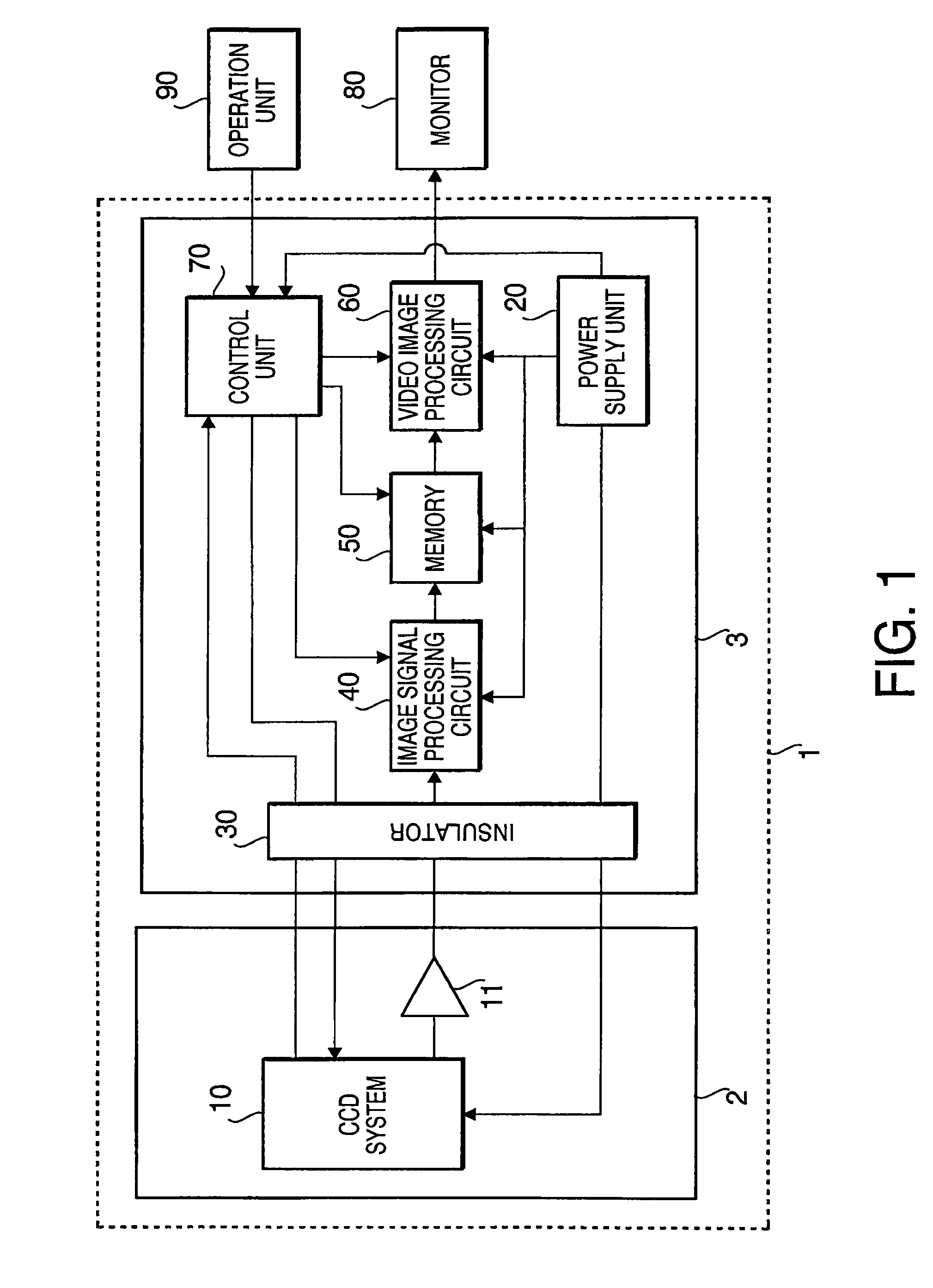
[0023]FIG. 1 is a function block diagram of an electronic endoscope 1 with a CCD control system according to an embodiment of the present invention. The electronic endoscope 1 includes a scope unit 2 and processor unit 3. The scope unit 2 and the processor unit 3 are connected by connector (not shown). An operation unit 90 and a monitor 80 are connected to the processor unit 3.

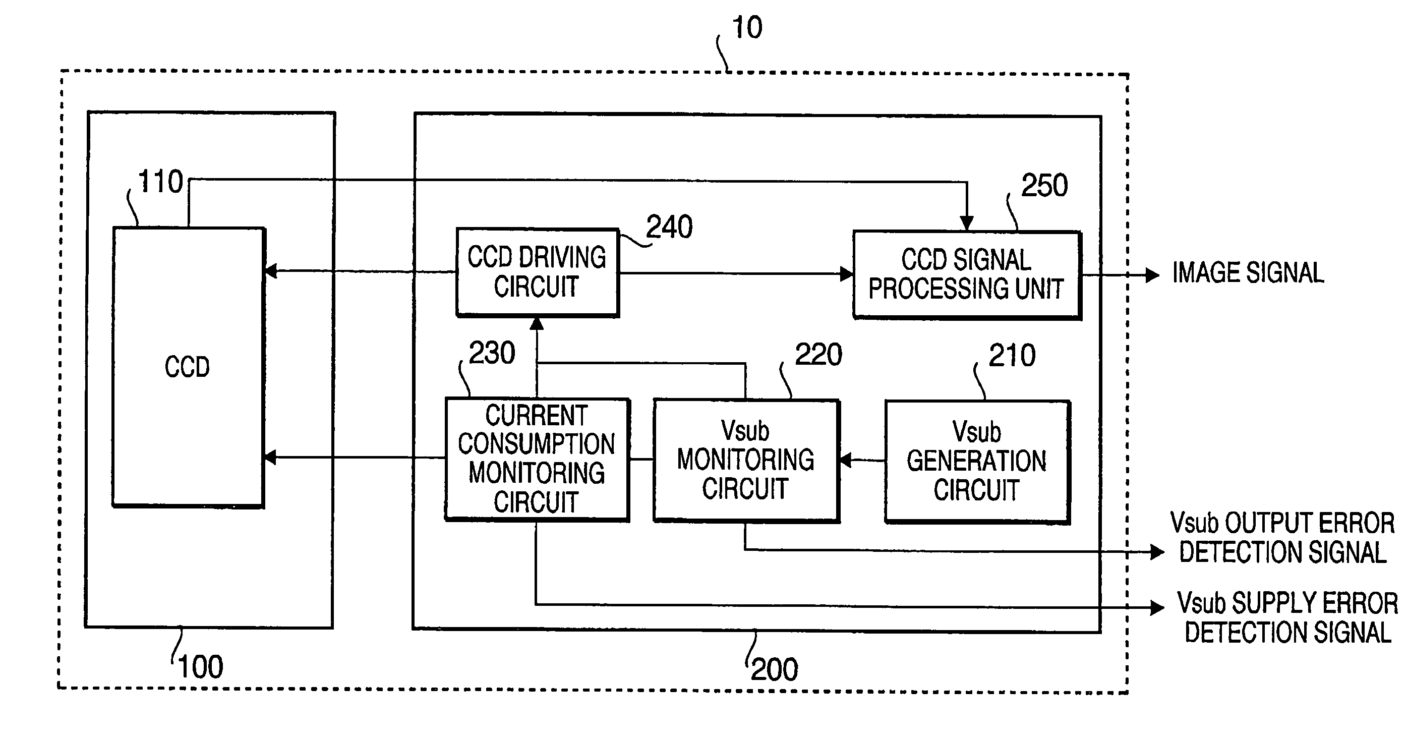
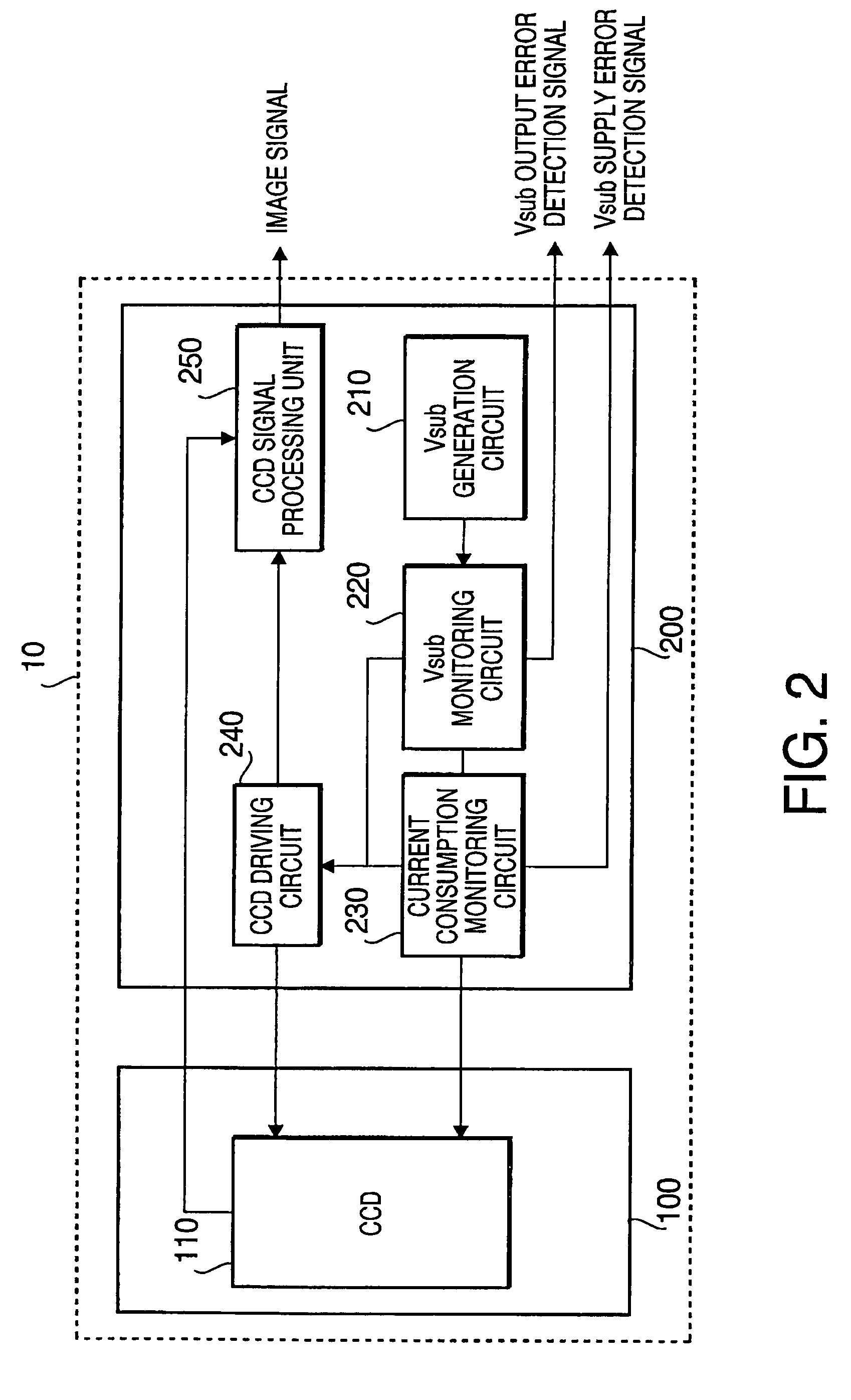
[0024]The scope unit 2 includes an insertion tube, an operation unit, a forceps insertion port, cables, connectors, etc. (not shown). The scope unit 2 includes therein a CCD system 10 having a CCD section 100 and a CCD control circuit 200 (see FIG. 2), a signal driving circuit 11 which transmits image signals from the CCD system 10, and various other sections such as a light guide, a forceps channel, an operation cable, an air line...


PUM


Abstract

An electronic endoscope is provided with a CCD control system which can prevent CCD breakage caused by a latchup, etc. by detecting a Vsub output error and a Vsub supply error without placing any device near the CCD. The endoscope system has a scope including a CCD placed at the scope's distal end, a driving section that supplies a drive signal to a CCD and drives the CCD and a bias voltage generation that generates a substrate bias voltage, a processor, a voltage monitoring section that monitors the voltage value of the substrate bias voltage, a current consumption monitoring section that monitors the current consumption corresponding to the substrate bias voltage, a drive stopping section that stops supplying the drive signal to the CCD when the voltage monitoring section or the current consumption section determines an error occurs.

Description

BACKGROUND OF THE INVENTION[0001]The present invention relates to a CCD control system for prevention of CCD breakage, and an endoscope which includes the CCD control system.[0002]CCD (Charge Coupled Device) is a device that can transform an optical image of a subject formed on a receiving surface into electric signals with an opt-electric conversion. Usually, the electric signals are processed by a signal processing section incorporated in the CCD control unit outside the device, and are output as image signals. It is necessary to supply various kinds of power voltages and clock pulses to drive the CCD. One of the power voltages is a substrate bias voltage (hereinafter referred to as Vsub). Vsub is the reference value of various electric potential distribution inside the device, and Vsub is generated by a Vsub generation circuit. CCDs fall into two classes: an internal Vsub generation type that CCD includes a Vsub generation circuit, and an external Vsub generation type that CCD is...

Claims


Application Information

Patent Timeline
Patent Type & Authority Patents(United States)
IPC IPC(8): H04N5/335A61B1/04H04N5/225H04N5/372H04N5/376
CPCH04N5/335H04N2005/2255H04N23/555H04N25/00
Inventor SUDA, TADAAKI
Owner HOYA CORP
Why Eureka
Try Eureka