Method for video coding artifacts concealment

a technology of video coding and artifacts, applied in the field of video decompression, can solve the problems of visual disturbing coding artifacts, distinguishing discontinuities generated from coding (i.e., coding artifacts), and real edges in a decoded, and achieves efficient memory access, low computational complexity, and reduced coding artifacts

Active Publication Date: 2009-09-22
AVAGO TECH INT SALES PTE LTD
View PDF7 Cites 13 Cited by
  • Summary
  • Abstract
  • Description
  • Claims
  • Application Information

AI Technical Summary

Benefits of technology

[0008]The objects, features and advantages of the present invention include providing a system and method for video coding artifact concealment that may (i) effectively reduce coding artifacts, (ii) not introduce objectionable new artifacts, (iii) utilize a small amount of storage, (iv) allow efficient memory access and / or (v) have low computational complexity.

Problems solved by technology

Digital video compressed by most video coding standards, such as MPEG-1, MPEG-2 / H.262, H.263, MPEG-4, and MPEG-4 AVC / H.264, suffers from visually disturbing coding artifacts, including blocking artifacts, ringing artifacts, and mosquito artifacts.
The coding artifacts are especially noticeable at low bit rate video.
A known problem of the spatial filtering approach is distinguishing discontinuities generated from coding (i.e., coding artifacts) and real edges in a decoded picture.
Edge distinguishing has been proven to be very difficult, and in some cases, even impossible.
Also, the spatial filtering approach is not effective in reducing mosquito artifacts.
However, true motion vectors are often not available.
In particular, the motion vectors used in coding may not necessarily represent the true motions of objects.
Using incorrect motion vectors in temporal filtering can result in disturbing distortion of a picture.
Also, the temporal filtering approach is not effective in reducing blocking artifact and ringing artifact.
Furthermore, both the spatial filtering approach and the temporal filtering approach normally have high computational complexity.
The approach of adding random noise into a decoded picture is based on an observation that coding artifacts are disturbing to human visual system because the artifacts all have certain patterns that are either spatial or temporal.

Method used


Image

  • Method for video coding artifacts concealment
  • Method for video coding artifacts concealment
  • Method for video coding artifacts concealment

Examples


Embodiment Construction

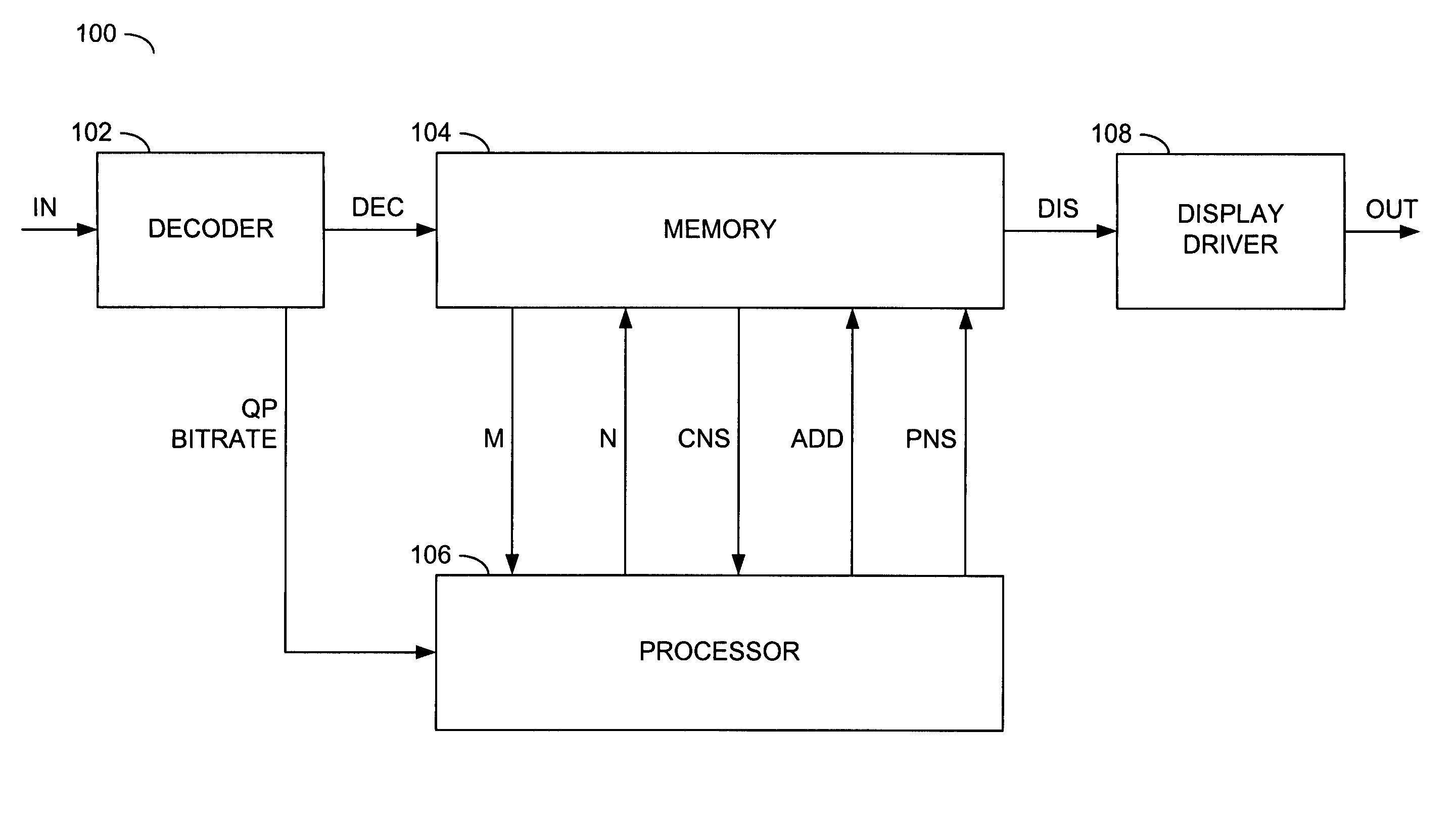
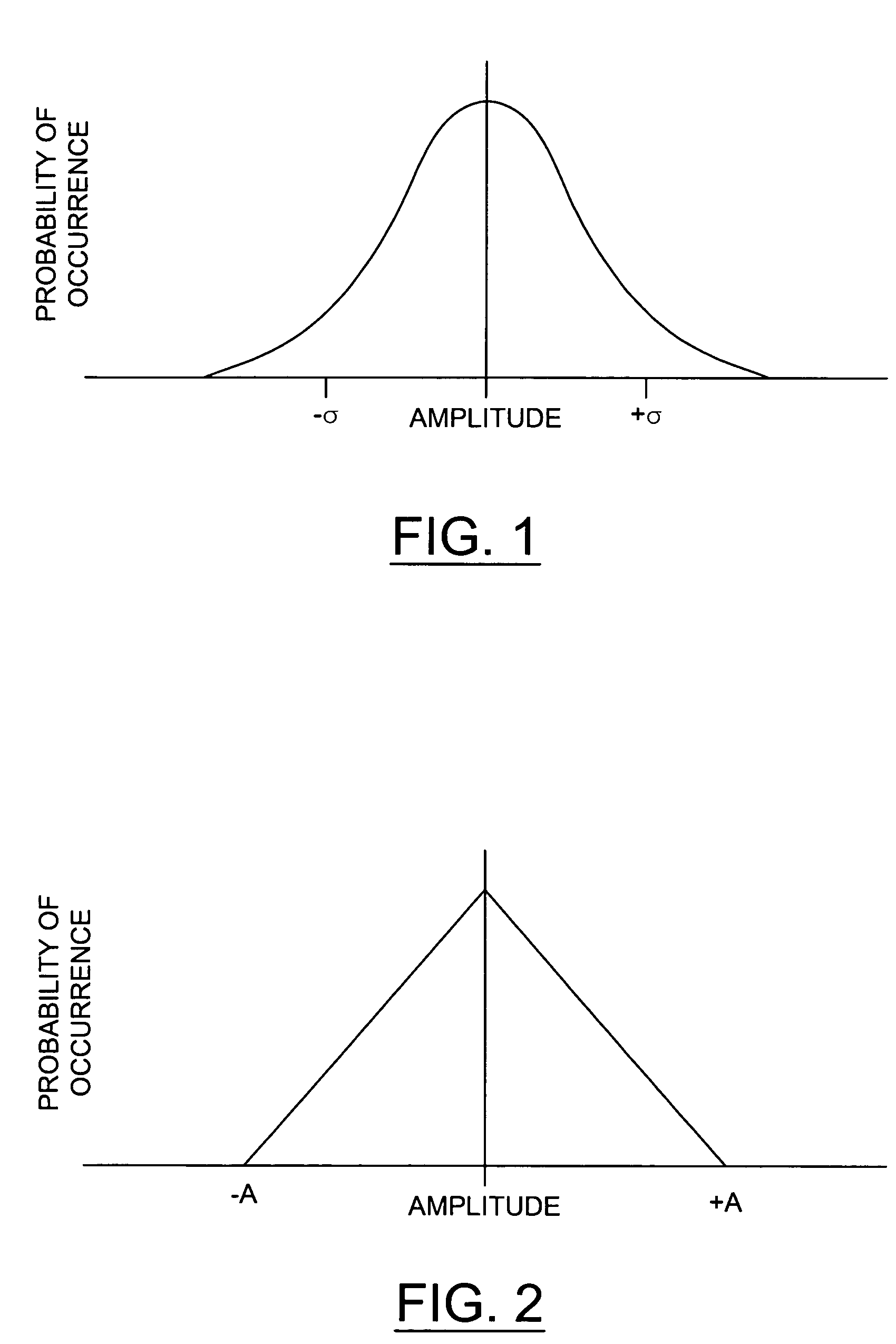
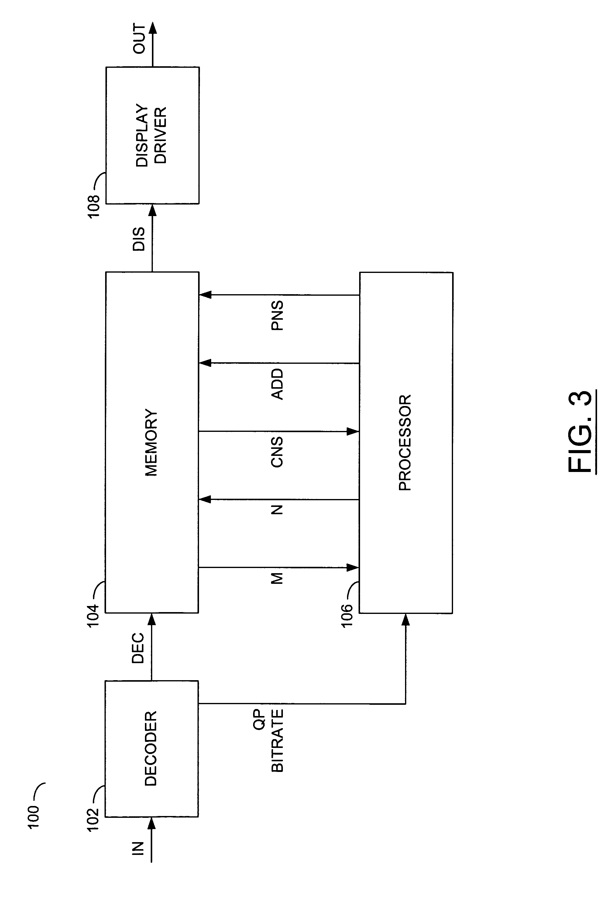
[0018]The present invention generally implements an approach of adding random noise into a decoded picture to conceal coding artifacts. The approach may consists of multiple steps. The steps may include pre-generating K random noise samples according to a specific probability distribution. Two example distributions may include (i) a Gaussian distribution (FIG. 1) with a zero mean and a standard deviation a and (ii) a triangular distribution (FIG. 2) between −A and +A, where A is a positive number. The randomly generated noise samples may be stored in a one-dimensional array (e.g., noise array G). For each block I in a decoded picture, a random number R may be generated. The random number R may be used as an offset in accessing the noise array G. Another step may include adding the noise samples starting from G[R] to the block I. The block I may define luminance values and / or chrominance values in the decoded picture. Note that the step of calculating the noise samples may be perform...


PUM


Abstract

A method and circuit for processing a reconstructed picture generated from compressed data is disclosed. The method generally includes the steps of (A) estimating a magnitude of coding artifacts created by a coding process for the compressed data based upon the compressed data, (B) generating a plurality of noise samples with a probability distribution over a range, the probability distribution determined by the magnitude and (C) adding the noise samples to the reconstructed picture for concealment of the coding artifacts.

Description

FIELD OF THE INVENTION[0001]The present invention relates to video decompression generally and, more particularly, to a method for video coding artifact concealment.BACKGROUND OF THE INVENTION[0002]Digital video compressed by most video coding standards, such as MPEG-1, MPEG-2 / H.262, H.263, MPEG-4, and MPEG-4 AVC / H.264, suffers from visually disturbing coding artifacts, including blocking artifacts, ringing artifacts, and mosquito artifacts. The coding artifacts are especially noticeable at low bit rate video. Reducing the coding artifacts in decoded video is highly desirable prior to displaying. A method to achieve an artifact reduction goal should be effective in reducing the coding artifacts, not introduce new objectionable artifacts and be easily implemented in terms of storage capacity, memory bandwidth and computational complexity.[0003]Three approaches to reducing coding artifacts currently exist: spatial filtering, temporal filtering and random noise addition. The spatial fi...

Claims


Application Information

Patent Timeline
Patent Type & Authority Patents(United States)
IPC IPC(8): H04N7/12H04N5/217H04N7/26
CPCH04N19/90
Inventor JIA, YUNWEIWINGER, LOWELL L.
Owner AVAGO TECH INT SALES PTE LTD
Why Eureka
Try Eureka