Recovery and relocation of a distributed name service in a cluster filesystem

a name service and filesystem technology, applied in the field of data storage, can solve the problems of inability to share data as easily and quickly, cumbersome and unacceptably slow process, and infancy of software technologies that enable true data sharing, and achieve the effect of improving recovery

Active Publication Date: 2009-09-22
HEWLETT-PACKARD ENTERPRISE DEV LP +1
View PDF3 Cites 14 Cited by
  • Summary
  • Abstract
  • Description
  • Claims
  • Application Information

AI Technical Summary

Benefits of technology

[0010]It is yet another aspect of the present invention to improve recovery in the event of failure of system(s) or component(s) in a cluster through management of a distributed name service that protects and preserves a level of control which ensures continued data integrity.

Problems solved by technology

However, the software technologies that enable true data sharing are mostly in their infancy.
While SANs offer the benefits of consolidated storage and a high-speed data network, existing systems do not share that data as easily and quickly as directly connected storage.
Data sharing is typically accomplished using a network filesystem such as Network File System (NFS™ by Sun Microsystems, Inc. of Santa Clara, Calif.) or by manually copying files using file transfer protocol (FTP), a cumbersome and unacceptably slow process.
While the same approach could be transferred to a SAN using much the same protocols, that would fail to eliminate the fundamental limitations of the file server or take advantage of the true benefits of a SAN.
The file server is often a bottleneck hindering performance and is always a single point of failure.
If multiple systems assume they have control of the filesystem and cache filesystem metadata, they will quickly corrupt the filesystem by, for instance, allocating the same disk space to multiple files.
On the other hand, implementing a filesystem that does not allow data caching would provide unacceptably slow access to all nodes in a cluster.
However, none of these products are known to provide direct read and write over a Fibre Channel by any node in a cluster.
However, if there are five machines, each accessing the same file, there will be five separate events and there is nothing tying those DMAPI events together.

Method used


Image

  • Recovery and relocation of a distributed name service in a cluster filesystem
  • Recovery and relocation of a distributed name service in a cluster filesystem
  • Recovery and relocation of a distributed name service in a cluster filesystem

Examples


Embodiment Construction

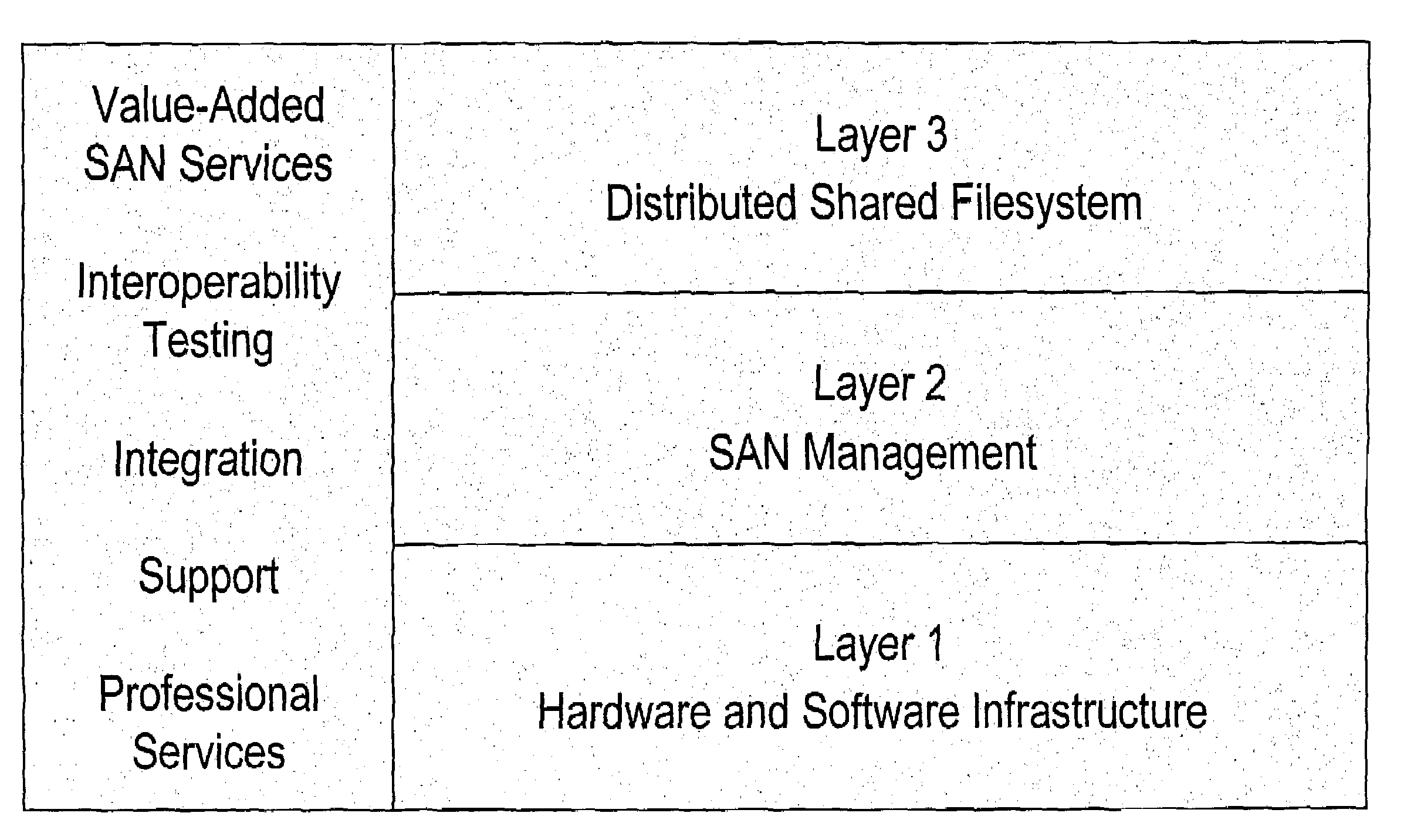
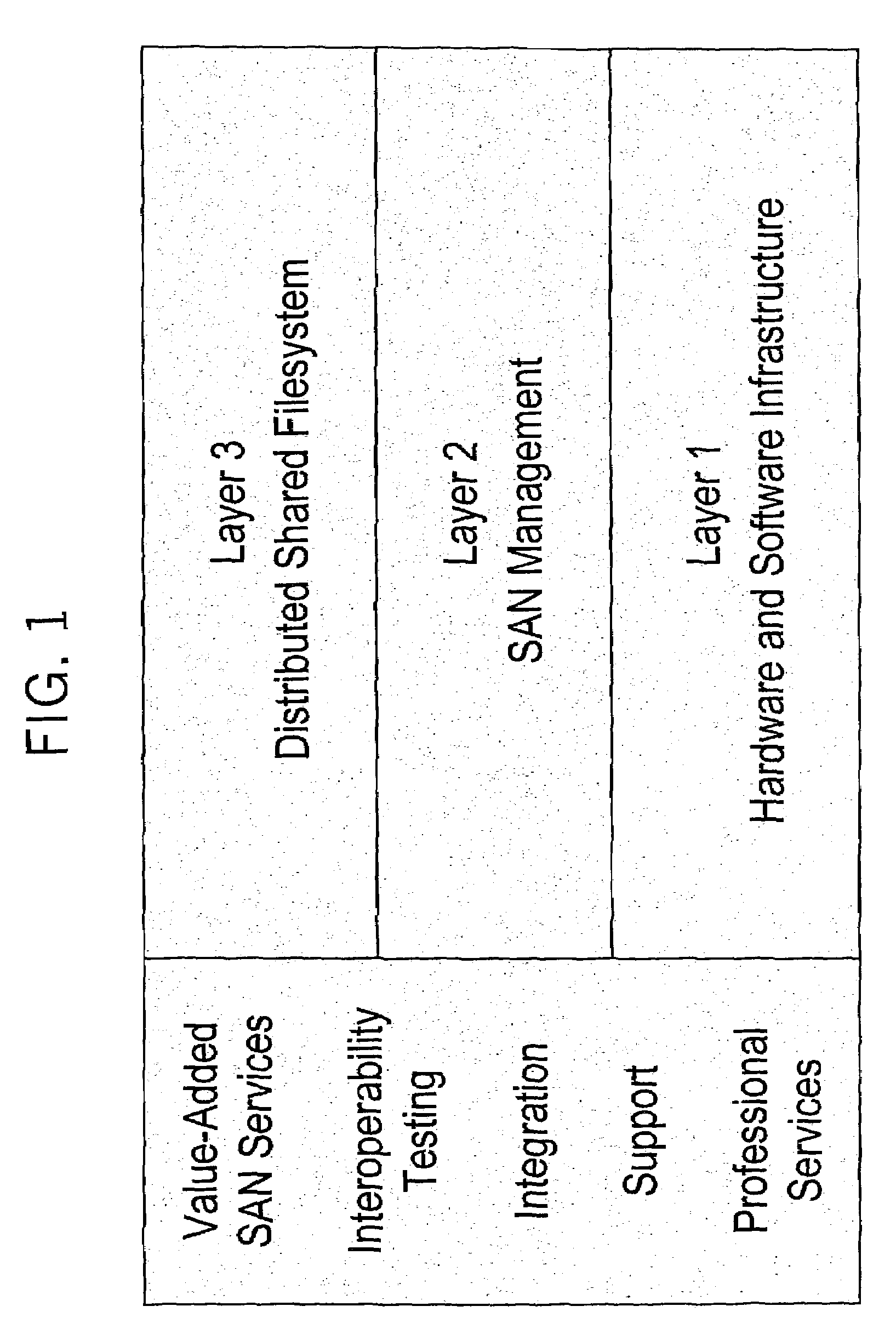
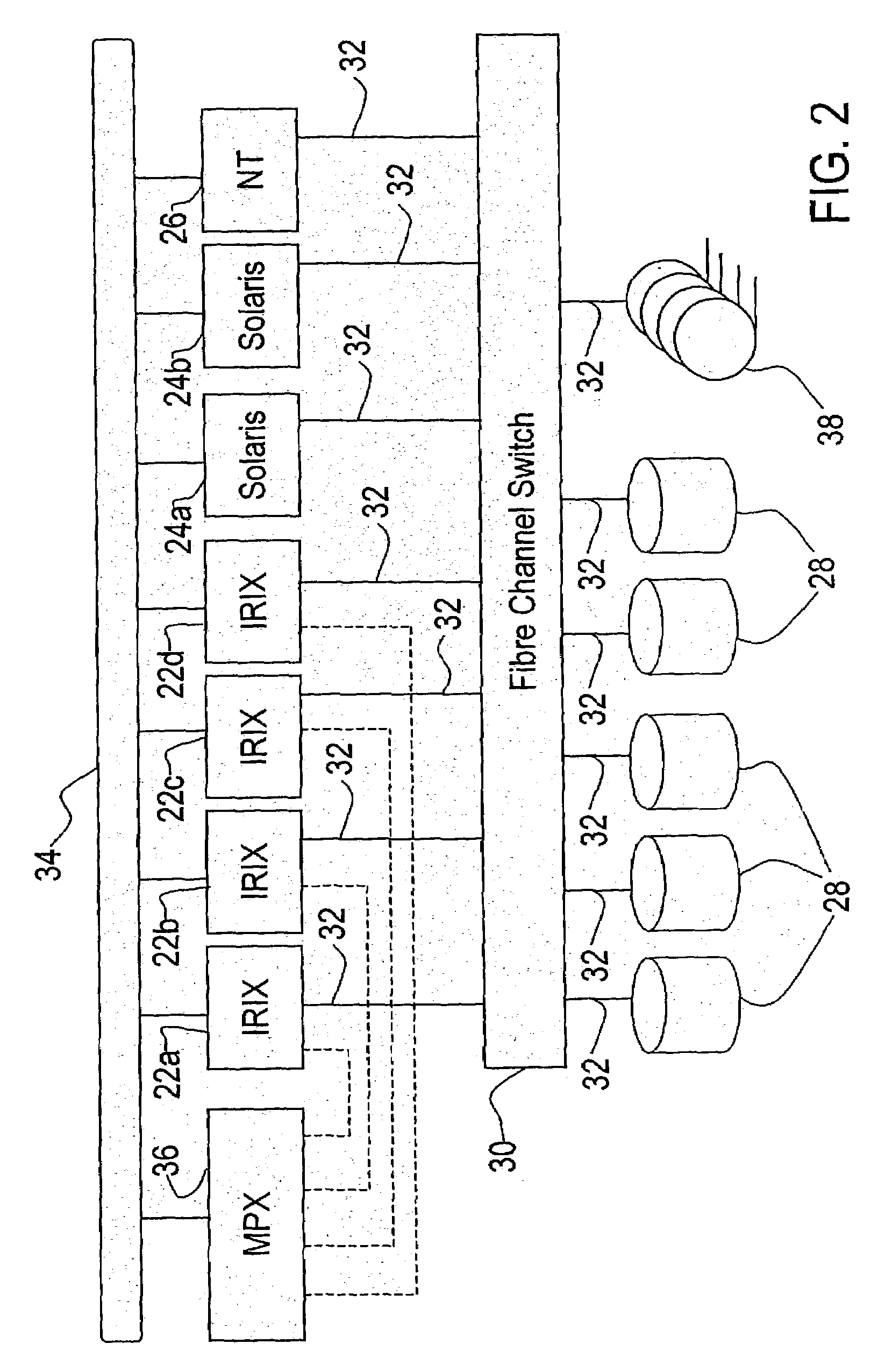
[0028]Following are several terms used herein that are in common use in describing filesystems or SANs, or are unique to the disclosed system. Several of the terms will be defined more thoroughly below.

[0029]

bagindefinitely sized container object for tagged databehavior chainvnode points to head, elements are inode, and vnodeoperationscfs or CXFScluster file system (CXFS is from SiliconGraphics, Inc.)chandleclient handle: barrier lock, state information and anobject pointerCMScell membership servicesCORPSEcommon object recovery for server endurancedcvnfile system specific components for vnode in client,i.e., inodeDMAPIdata migration application programming interfaceDNSdistributed name service, such as SGI's white pagesdsvncfs specific components for vnode in server, i.e., inodeheartbeatnetwork message indicating a node's presenceon a LANHSMhierarchical storage managementinodefile system specific information, i.e., metadataKOREkernel object relocation enginemanifestbag including obje...


PUM


Abstract

A cluster of computer system nodes share direct read/write access to storage devices via a storage area network using a cluster filesystem. During relocation of a server for a distributed name service and recovery of a cluster, entries related to the distributed name service for filesystems is updated. During relocation, a new server for a filesystem informs all nodes in the cluster of the new server's location. During recovery, a process executing on each node deletes entries related to the distributed name service for any filesystem that does not have a server in the recovering cluster.

Description

CROSS-REFERENCE TO RELATED APPLICATION(S)[0001]This application is a continuation-in-part of U.S. patent application entitled CLUSTERED FILE SYSTEM having Ser. No. 10 / 162,258, by Costello et al., filed Jun. 5, 2002 now U.S. Pat. No. 6,950,833, which claims the benefit of U.S. provisional patent application entitled CLUSTERED FILE SYSTEM having serial No. 60 / 296,046, by Bannister et al., filed Jun. 5, 2001, both incorporated by reference herein.BACKGROUND OF THE INVENTION[0002]1. Field of the Invention[0003]The present invention is related to data storage, and more particularly to a system and method for accessing data within a storage area network.[0004]2. Description of the Related Art[0005]A storage area network (SAN) provides direct, high-speed physical connections, e.g., Fibre Channel connections, between multiple hosts and disk storage. The emergence of SAN technology offers the potential for multiple computer systems to have high-speed access to shared data. However, the softw...

Claims


Application Information

Patent Timeline
Patent Type & Authority Patents(United States)
IPC IPC(8): G06F17/30H04L29/08
CPCH04L67/1095H04L69/329H04L67/1097Y10S707/99952
Inventor BECK, KEN
Owner HEWLETT-PACKARD ENTERPRISE DEV LP
Why Eureka
Try Eureka