Vibration exciter

a technology of vibration exciter and exciter body, which is applied in the direction of mechanical energy handling, electrical equipment, support/enclose/case, etc., can solve the problems of requiring a lot of space, damage to adjacent buildings, and gear mechanisms or oscillating gear trains, so as to increase the torque of the oscillating motor, increase the speed of rotation, and increase the effect of the effective utilization of construction spa

Inactive Publication Date: 2009-10-06
ABI +1
View PDF5 Cites 23 Cited by
  • Summary
  • Abstract
  • Description
  • Claims
  • Application Information

AI Technical Summary

Benefits of technology

[0007]This is where the invention provides a remedy. It is an object of the invention to provide a vibration exciter in which the effective imbalance, and therefore the vibration, is adjustable, and which furthermore has a compact construction. According to the invention, this task is accomplished by a vibration exciter comprising at least two axles disposed parallel to one another, as well as at least two imbalance masses, which are attached to one or more of the axles. There are means for adjusting the relative rotary position of the imbalance masses relative to one another. These means comprise at least one rotary oscillating motor having a rotor shaft and a stator housing. The rotor shaft is an integral part of one of the axles, and the rotary position of the stator housing relative to the rotor shaft can be changed. The rotor oscillating motor has means for locking the stator housing to the rotor shaft.
[0008]With the invention, a vibration exciter is created in which the effective imbalance, and therefore the vibration, is adjustable, and which furthermore has a compact construction. The use of the rotor oscillating motor allows a relative adjustment of the imbalance masses relative to one another, without any conversion of a linear movement into a rotary movement being required, thereby achieving a compact construction. A position change due to internal leakage is prevented by the means for locking the stator housing onto the rotor shaft. Since the hydraulic pressure can be lowered in the locked state of the stator housing, seals are under clearly less stress, and this results in a reduced wear of the seals, since the press-down forces are clearly less in the pressure-free state. This saves energy, since no adjustment or re-adjustment of the oscillating motor is required over the period of operation of the vibrator. Furthermore, the required regulation of the oscillating motor is simplified.
[0009]In an embodiment of the invention, at least one shaft seal is disposed between rotor shaft and stator housing, which seal is provided with a support element. In this way, external leaks at the shaft seals are avoided in an operating state with low operating pressure. Lifting of the sealing edge of the shaft seal, at high speeds of rotation or vibrations, is mechanically prevented by the support element. Preferably, the shaft seal is hydraulically biased.

Problems solved by technology

If the soil is excited in the resonance range, the amplitude of the soil vibration becomes very great, and this can result in damage to adjacent buildings.
Known solutions such as planetary gear mechanisms or oscillating gear trains require a lot of space, are not well suited for high speeds of rotation, and produce a high noise level because of additional gear wheels.

Method used


Image

  • Vibration exciter
  • Vibration exciter
  • Vibration exciter

Examples


Embodiment Construction

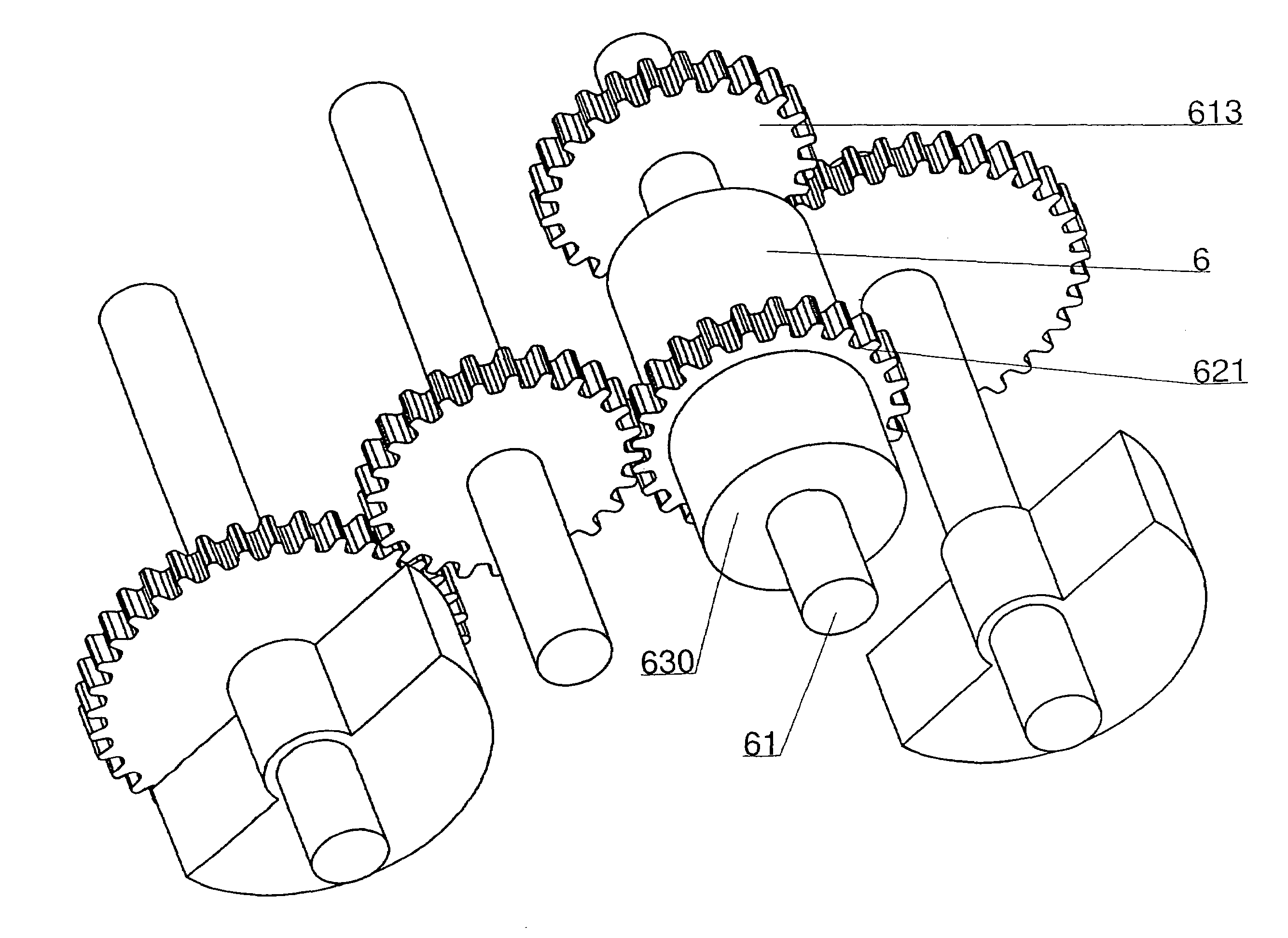
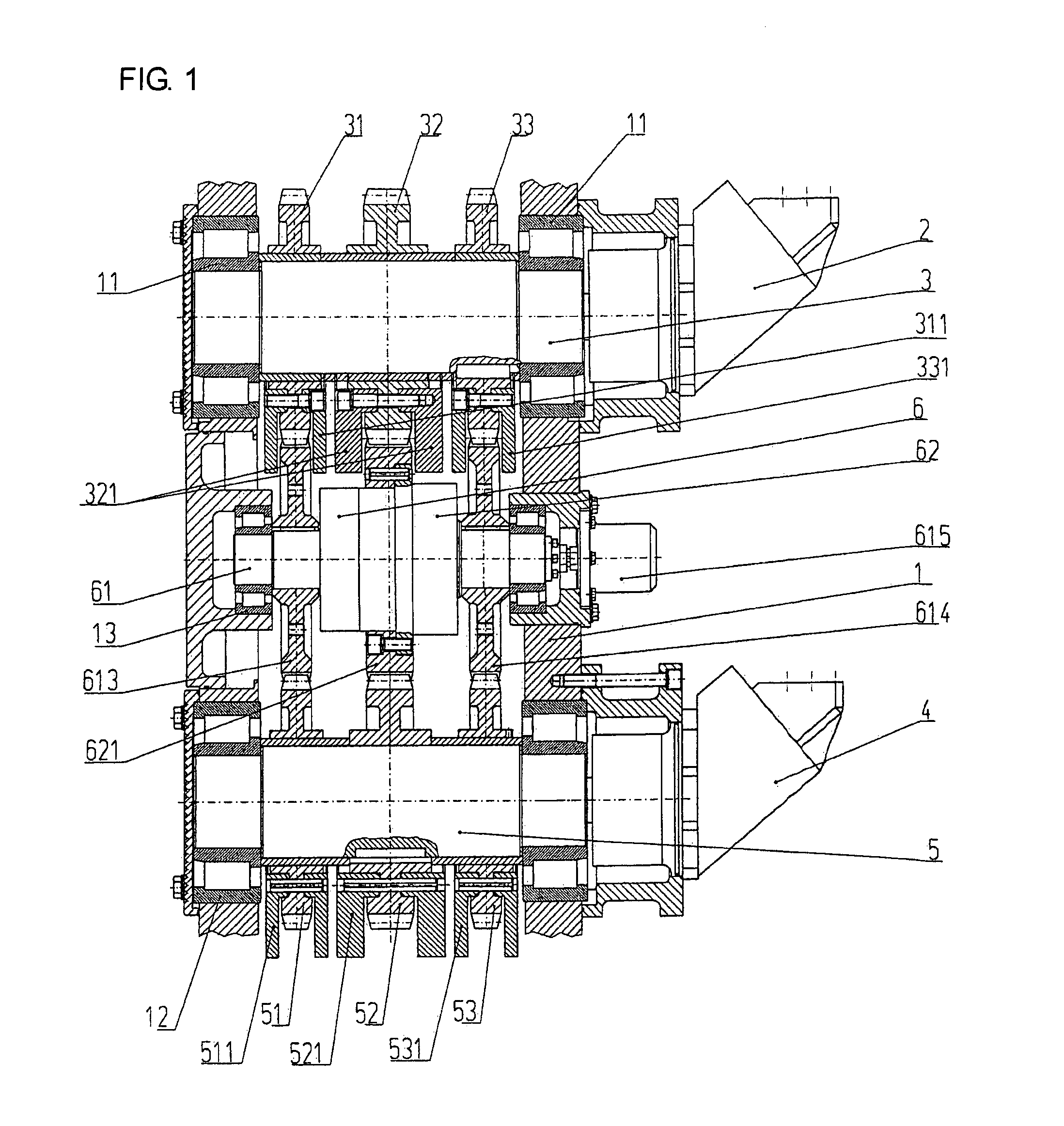
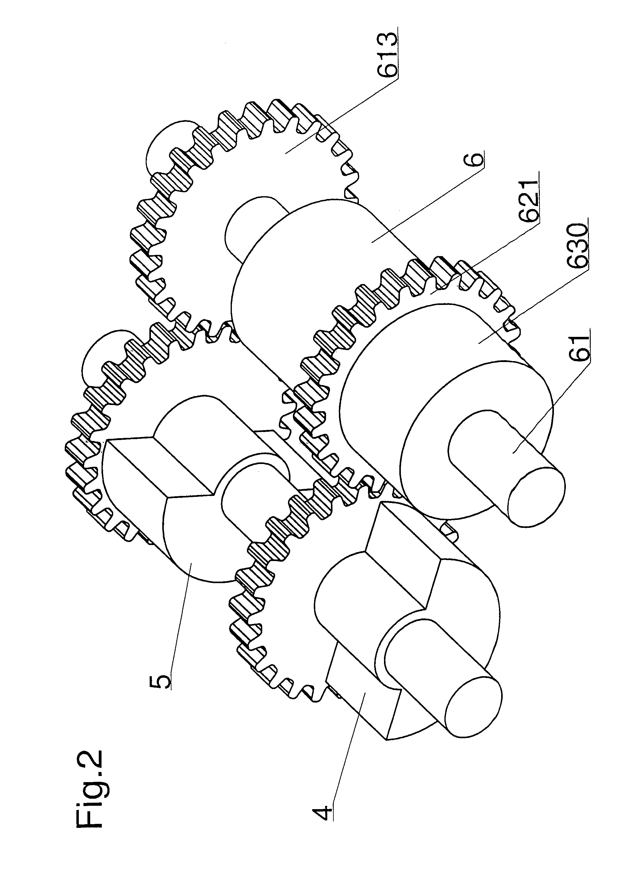
[0029]Referring now in detail to the drawings, the vibration generator selected as an exemplary embodiment is configured as a vibrator gear mechanism, as shown in FIG. 1. It essentially consists of a housing 1 in which two shafts 3, 5 provided with gear wheels 31, 32, 33 and 51, 52, 53, respectively, are mounted to rotate, as well as of an oscillating motor 6, the rotor shaft 61 of which is provided with gear wheels 613, 614, and the stator housing 62 of which is provided with a gear wheel 621.

[0030]Shaft 3 is mounted to rotate in bearings 11 of housing 1. An outer gear wheel 31 is disposed on shaft 3, mounted to rotate; and opposite outer gear wheel 33 is connected to rotate with shaft 3. Gear wheels 31, 33 are provided with imbalance masses 311, 331, in each instance. In the center between gear wheels 31, 33, a gear wheel 32 is furthermore disposed on shaft 3, mounted to rotate. Gear wheel 32 is also provided with an imbalance mass 321. In the exemplary embodiment, shaft 3 is conn...


PUM


Abstract

A vibration exciter has at least two axles disposed parallel to one another, as well as at least two imbalance masses, which are attached to one or more of the axles. The relative rotary position of the imbalance masses can be adjusted relative to one another by a rotary oscillating motor having a rotor shaft and a stator housing. The rotor shaft is an integral part of one of the axles, and the rotary position of the stator housing relative to the rotor shaft can be changed. The stator housing can be locked to the rotor shaft. The oscillating motor has a rotor shaft and a stator housing, between which working chambers are formed. The stator housing can rotate about the rotor shaft and can be locked relative to the rotor shaft.

Description

BACKGROUND OF THE INVENTION[0001]1. Field of the Invention[0002]The invention relates to a vibration exciter. The invention furthermore relates to an oscillating motor for use in a vibration exciter.[0003]2. The Prior Art[0004]In construction, vibration generators such as vibrators, shakers, or vibratory pile drivers are used to introduce or draw profiles into the ground, or also to compact soil material. The ground is excited by vibration, and thereby achieves a “pseudo-fluid” state. The goods to be driven in can then be pressed into the construction ground by a static top load. The vibration is characterized by a linear movement and is generated by rotating imbalances that run in opposite directions, in pairs, within a vibrator gear mechanism. Vibration generators characterized by the imbalance that is installed (referred to as “static moment” in technical circles) and by the maximal speed of rotation.[0005]In order to achieve an optimal advance and good compacting, as a function ...

Claims


Application Information

Patent Timeline
Patent Type & Authority Patents(United States)
IPC IPC(8): H02K7/06
CPCB06B1/166Y10T74/18056
Inventor HEICHEL, CHRISTIANKLEIBL, ALBRECHTHENSE, FRANKWINZEN, ROLF
Owner ABI
Why Eureka
Try Eureka