Relay with self-resilient contact bridge

a self-resilient, contact technology, applied in the field of relays, can solve the problems of contact interruption, contact face burnout, contacts fusing to one another, etc., and achieve the effect of worsening the contact-making process

Active Publication Date: 2009-10-06
SEG AUTOMOTIVE GERMANY GMBH
View PDF17 Cites 10 Cited by
  • Summary
  • Abstract
  • Description
  • Claims
  • Application Information

AI Technical Summary

Benefits of technology

[0004]By comparison, the invention offers the advantage that the contact bridge is embodied as self-resilient and has a curved embodiment, which under the contact pressure that occurs in the switching actuation allows a reversible change in shape of the contact bridge, and in particular a (for instance slight) widening of the curved shape. Widening of the curved shape is intended to mean that the curved contour—as viewed in longitudinal section—flattens out; the end pieces of the curve accordingly have a greater spacing from one another in the deformed state. The change in shape is caused by the fact that the end pieces of the curve meet the contact faces of the counterpart contacts, causing a vector shift in the compression force that exerts the contact pressure, such that a transverse force component occurs. The result is sliding or chafing of the ends of the curve on the contact faces of the counterpart contacts; the chafing motion of the two ends of the curve extends outward and diametrically opposite, when the curved contour flattens as described above. Upon closure of the contacts, the contact faces of the contact bridge accordingly become seated on the face of the counterpart contacts, and (in the ensuing pressing of the contact bridge) are pressed slightly outward in a gentle course of motion. Because of the self-resilience of the contact bridge, which is due to the curved contour and to the properties of the material, and over the course of the actual first contact closure, the above-described, outward-oriented chafing of the contact faces on one another occurs. This is associated with cleaning of the contact faces on the contact bridge and on the associated counterpart contacts which occurs simultaneously with the contact closure and which persists over the entire service life of the relay. The chafing contact touch in the course of the seating on the contact faces removes surface substrates that are present, especially oxides and / or sulfates, by mechanical action. Moreover, because of the self-resilient embodiment and the “overpressing” of the contact bridge that lasts beyond the instant of the first actual contact closure, a burnoff reserve is formed. Even severely worn (burned-off) contacts, because of the chafing seating process, make reliable contact over a large area. This extensively assures clean, reliable contact closure.
[0006]In a further preferred embodiment, the contact compression spring and contact plate are adapted to one another in shape. This means that the structural shapes of the two components are adapted to one another in such a way that the most favorable possible structural dimensions, the most economical possible manufacture, and the best possible fit accuracy are obtained.
[0007]In an especially preferred embodiment, it is provided that the contact compression spring is embodied as a spring plate. The term spring plate is understood to mean a spring which develops its spring properties substantially transversely to its two-dimensional extent. Using it makes the structural size of the relay smaller.
[0013]In a preferred embodiment, a rotary alignment and / or fixation device is provided, which defines the contact compression spring, the contact plate, or both in their relative position with respect to the contact bridge holder. To that end, the opening described above, for instance, which is not circular but oval or embodied in some other geometrically suitable way in the contact plate and the contact spring, not only forms a material extension acting as a current-carrying capacity amplification zone and as a rotary alignment and / or fixation device of the contact place and the contact compression spring relative to one another, but moreover makes it possible to insert the contact bridge holder through the contact bridge, so that precisely because of the rotary alignment and / or fixation device, the contact bridge is seated in a precisely defined position on the contact bridge holder. The cross-sectional geometry of the contact bridge holder in the seating plane of the contact bridge and the geometry of the opening in the contact bridge correspond to one another.
[0014]It is also preferably provided that the contact bridge, seated in this way on the contact bridge holder, be retained on the contact bridge holder by means of a clamping disk. The clamping disk is understood to be a component which is slipped, by means of an opening located in it, onto the end of the contact bridge holder that holds the contact bridge; peripheral regions of the opening that are embodied in the form of tabs or teeth, for instance, bend outward in the direction of the insertion motion of the contact bridge holder and in the process notch into tree material comprising the contact bridge holder. The result is a blocking action in the direction extending opposite the insertion motion. The contact bridge is consequently fixed on the inserted end of the contact bridge holder. It is thus assured that the contact bridge has a precisely defined location inside the relay arrangement, so that loosening or slippage or longitudinal and / or axial play relative to the axis of the switching motion can as much as possible be precluded. It can thus be prevented that the outer contour of the contact bridge will scrape or scratch the relay housing or switch cap, for instance, causing abrasion of housing material, which could spoil the contact faces and worsen the contact- making process. This also assures that the switching event will be executed without hindrance from external mechanical braking or blocking factors caused by the scraping of the contact bridges on the relay housing or switch cap.
[0015]In an especially preferred embodiment, it is provided that the contact bridge, to embody its curved shape—viewed in longitudinal section—be embodied approximately in a U shape, and that the free ends of the legs of the U be made to extend curving outward. Such an embodiment makes it possible for the ends of the legs to have a shaping which promotes the above-described sliding-on motion onto the contact faces of the counterpart contacts and that necessarily predetermines the direction of the sliding motion.

Problems solved by technology

This causes burnoff of the contact faces, and under some circumstances, especially with worn contacts, it causes the contacts to fuse to one another in the closed state, because of the severe heating caused by the spark.
In the case of the aforementioned recoiling event, contact interruptions occur as well as (because of the recoiling event) increased sparking.
It is also disadvantageous in these constructions that contact wear, for instance from burnoff, worsens the contact position; in other words, the contact faces of the contact bridge and of the associated counterpart contacts no longer touch over their full surface.
Another disadvantage of the prior art is that the cylindrical contact compression spring in conventional contact systems occupies a relatively large amount of installation space and disadvantageously determines the axial structural length of the relay.

Method used


Image

  • Relay with self-resilient contact bridge
  • Relay with self-resilient contact bridge
  • Relay with self-resilient contact bridge

Examples


Embodiment Construction

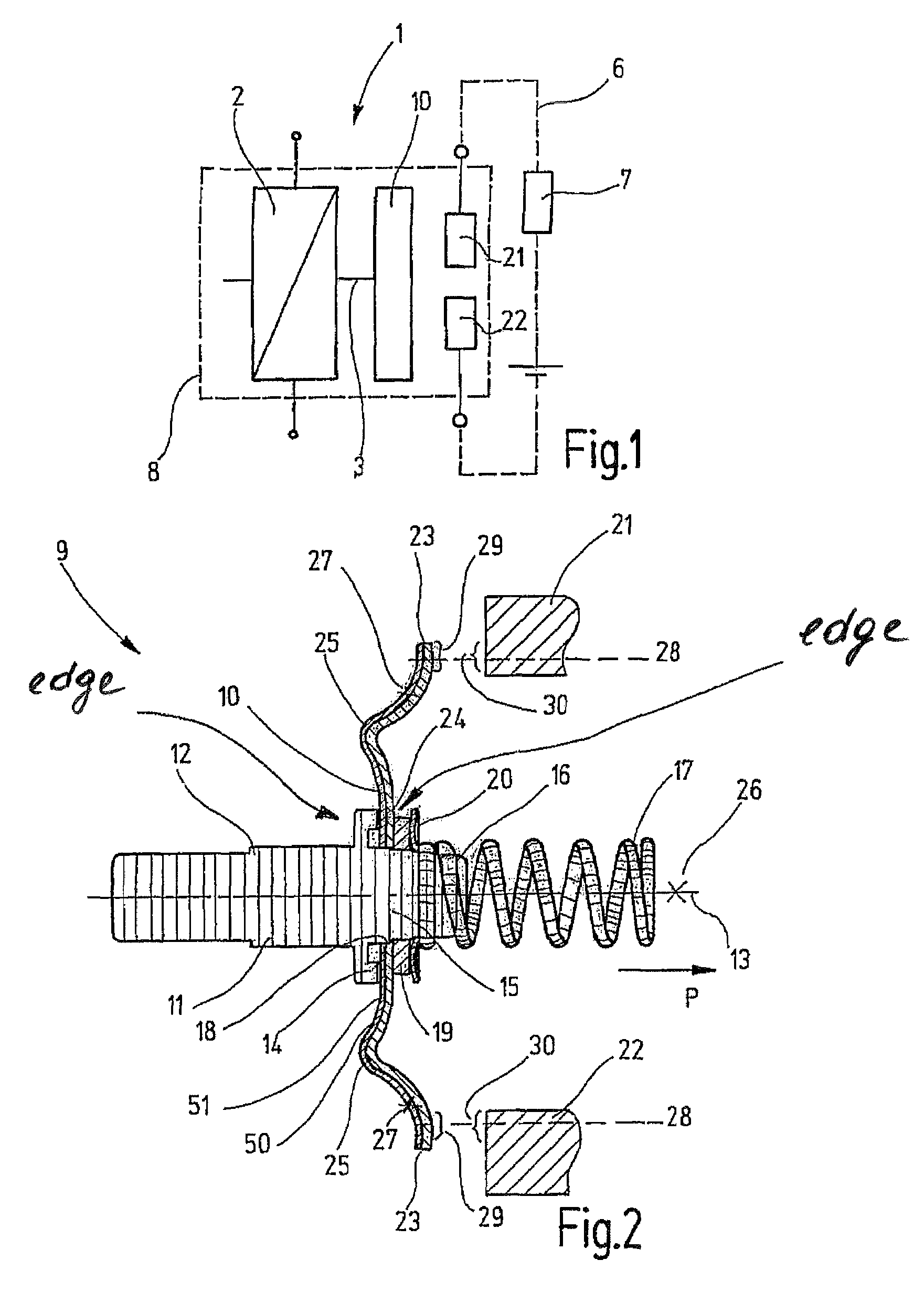
[0024]FIG. 1 schematically shows a relay 1 with a magnet coil 2 and an armature 3. A contact bridge 10 is associated with the armature 3. The contact bridge 10 cooperates with two counterpart contacts 21 and 22. A load current circuit 6 with at least one consumer 7 is also shown symbolically. The relay 1 has a housing 8, shown only schematically. Upon excitation of the magnet coil 2, the armature 3 is actuated and causes the closure of the load current circuit 6, by moving the contact bridge 10 until it rests on the counterpart contacts 21 and 22.

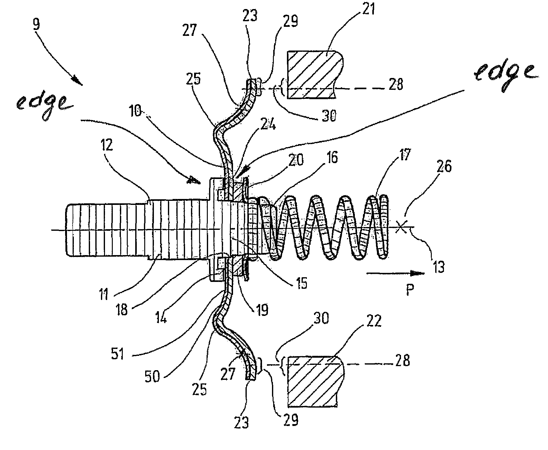
[0025]FIG. 2 shows the region of the relay 1 that is relevant to the invention, namely a contact bridge assembly 9, comprising a contact bridge 10 and a contact bridge holder 11 that is embodied as a switching pin 12. The switching pin 12 extends coaxially to the switching axis 13. The contact bridge holder 11 has a contact bridge bearing surface 14 and a contact bridge receptacle 15 that extends coaxially to the switching axis 13. The cont...


PUM


Abstract

A relay, in particular for a starter for an internal combustion engine for use in a motor vehicle. The relay has a self-resilient contact bridge, which for a reversible change in shape effected by the contact pressure, in particular widening, is embodied in curved form.

Description

FIELD OF THE INVENTION[0001]The invention relates generically to a relay.BACKGROUND OF THE INVENTION[0002]Relays are known. They have contact bridges that cooperate with associated counterpart contacts in order to close a load current circuit that is to be switched. Relays for internal combustion engine starters, because of the high currents to be switched, have contact bridges, which because of the high current-carrying capacity required have a large conductor cross section. Because of the large conductor cross section, the contact bridges are embodied as substantially solid. In the prior art, it is known to position such contact bridges vertically to the switching axis on a contact bridge holder that makes a defined switching actuation possible by means of a compression spring (spiral spring) and a contrarily acting restoring spring. The contact bridge is electrically disconnected by an insulating bush from the components that support it, in particular the contact bridge holder an...

Claims


Application Information

Patent Timeline
Patent Type & Authority Patents(United States)
IPC IPC(8): H01H1/00H01H1/20H01H1/26H01H50/20H01H50/54H01H51/06H01H67/02
CPCH01H1/20H01H51/065H01H1/26
Inventor BRAUN, HANSWEIGT, JOSEFFUHR, STEFFEN
Owner SEG AUTOMOTIVE GERMANY GMBH
Why Eureka
Try Eureka