Electrical machine having symmetrical coil sections

a technology of symmetrical coil sections and electric machines, applied in the field of electric machines, can solve problems such as unsatisfactory motor noise, and achieve the effect of reducing motor noise and smoother motor operation

Inactive Publication Date: 2009-10-13
ROBERT BOSCH GMBH
View PDF7 Cites 2 Cited by
  • Summary
  • Abstract
  • Description
  • Claims
  • Application Information

AI Technical Summary

Benefits of technology

[0004]The two-poled electric machine according to the invention and its manufacturing method, with the defining characteristics of the independent claims, have the advantage that the simultaneous commutation of the two symmetrically situated coil sections compensates for the radial force components of the two coil sections when they are supplied with current. Such a symmetrical arrangement of the two coil sections in relation to the rotation axis makes it possible with a simultaneous flow of current through the coil sections, to achieve a smoother motor operation, which significantly reduces the motor noise.
[0013]In order to assure the most uniform possible flow of current during commutation, the brushes are embodied so that as the commutator rotates, they each overlap two adjacent laminations so as to short circuit them. This makes it possible to significantly reduce brush sparking.
[0014]It is advantageous to embody the coil sections in the form of a double winding equipped with two approximately parallel coil wires with a reduced cross section. This makes it possible to achieve a higher space factor of the grooves and therefore to increase the output of the electric motor without increasing production time.
[0015]The manufacturing method according to the invention for a two-poled electric machine with two coil sections situated symmetrically to each other can be used to easily manufacture a reduced-noise electric drive motor of the kind used, for example, in adjusting applications in motor vehicles. This does not require any appreciable increase in complexity compared to conventional winding methods, thus making it possible, in a cost-neutral fashion, to achieve a significant increase in the quality of the electric machine by reducing the amount of noise it generates.

Problems solved by technology

These virtually parallel coils, however, are supplied with current independently of each other so that when the coils are supplied with current during operation, radial force components are exerted on the armature, which generate undesirable motor noise.

Method used


Image

  • Electrical machine having symmetrical coil sections
  • Electrical machine having symmetrical coil sections
  • Electrical machine having symmetrical coil sections

Examples


Embodiment Construction

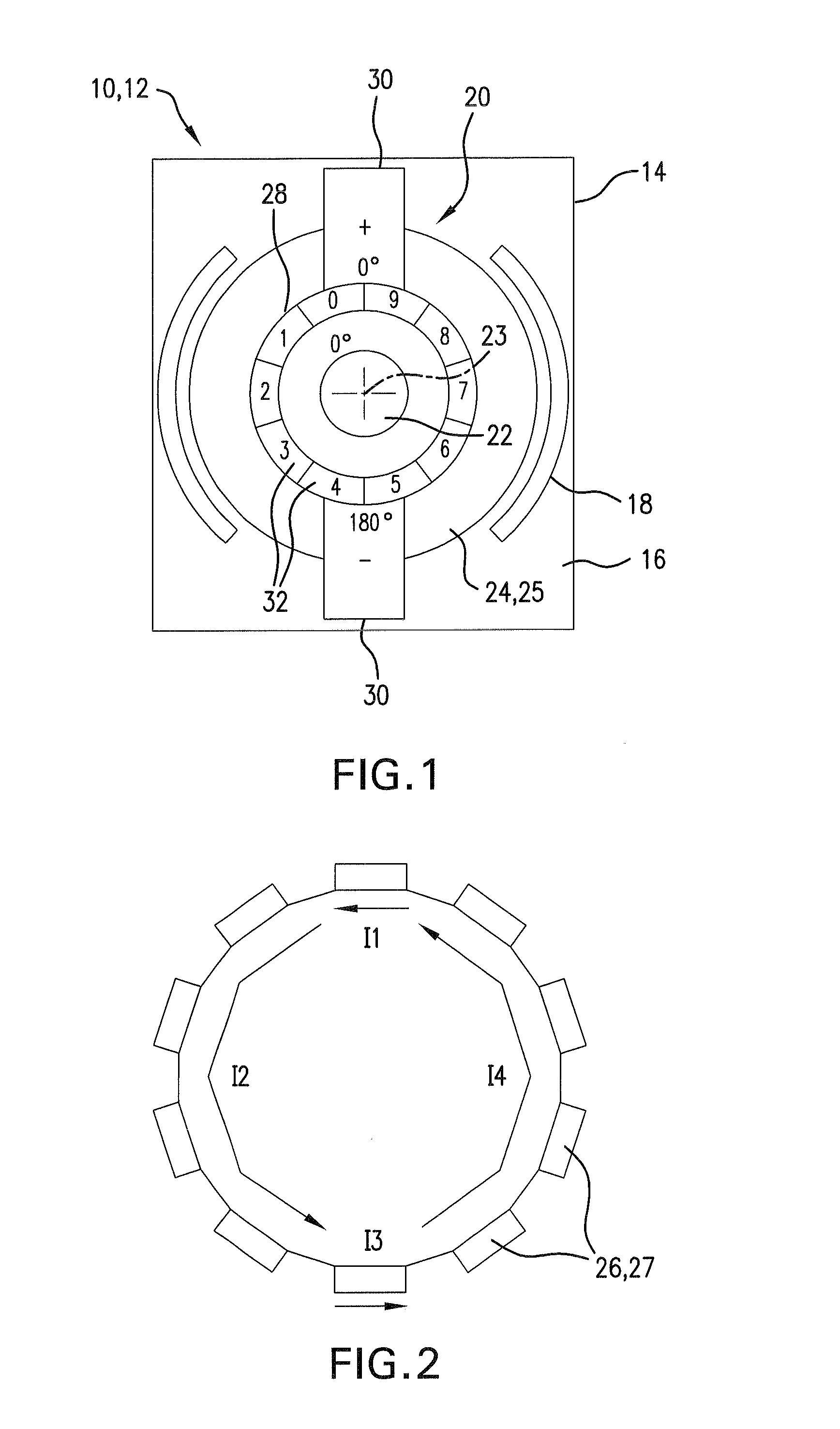
[0026]FIG. 1 schematically depicts a cross section through an electric machine 10 that is embodied in the form of a two-poled dc motor 12 in the exemplary embodiment. A housing 14 contains a stator 16, which is equipped with two permanent magnets 18 and cooperates with a rotor 20 that is supported so that it can rotate in the housing 14. The rotor 20 has a rotor shaft 22 and a laminated armature core 24 on which coils 26 are wound in the form of chords. The armature shaft 22 also supports a commutator 28 that can be electrically commutated via brushes 30. In the exemplary embodiment, the two brushes 30 are situated offset from each other by approximately 180° and are embodied in such a way that as the commutator 28 rotates in relation to the brushes 30, at the transition from one commutator lamination 32 to an adjacent commutator lamination 32, the brushes 30 short circuit the two laminations. The two brushes 30 are labeled with a plus and a minus that symbolize the flow of current ...


PUM

PropertyMeasurementUnit
diameteraaaaaaaaaa
diameteraaaaaaaaaa
angleaaaaaaaaaa

Abstract

The invention relates to an electrical machine (10), and to a method for producing such an electrical machine, especially for adjusting mobile parts in a motor vehicle. Said machine comprises a rotor (20) on which a bipolar electrical winding (25) having a plurality of coils (26) is arranged. Said coils (26) are configured to give two symmetrical coil sections (27) each which are disposed symmetrical to each other relative to the axis of rotation (23) of the rotor (20), both coil sections (27) being simultaneously commutable.

Description

CROSS REFERENCE[0001]The invention described and claimed hereinbelow is also described in German Patent Applications DE 10 2005 015 139.6 filed on Mar. 31, 2005 and DE 10 2005 035 411.4 filed on Jul. 28, 2005. This German Patent Application provides the basis for a claim of priority of invention under 35 U.S.C. 119(a)-(d).BACKGROUND OF THE INVENTION[0002]The present invention relates to an electric machine with a tool-poled electric winding.[0003]U.S. Reissue 27,893 disclosed an armature winding in an electric machine in which two coils are situated approximately in geometrically parallel fashion on a laminated armature core. Such an arrangement of the two coils is produced with a winding machine on which two coils can be wound at the same time by means of two flyers. These virtually parallel coils, however, are supplied with current independently of each other so that when the coils are supplied with current during operation, radial force components are exerted on the armature, whi...

Claims


Application Information

Patent Timeline
Patent Type & Authority Patents(United States)
IPC IPC(8): H02K23/34
CPCH02K3/28H02K23/30Y10T29/49009H02K3/16H02K3/00
Inventor ROOS, GERALD
Owner ROBERT BOSCH GMBH
Why Eureka
Try Eureka