Geospatial image change detecting system with environmental enhancement and associated methods

a technology of environmental enhancement and image change detection, applied in the field of image processing, can solve the problems of requiring a significant amount of time and labor, not well suited to modeling man-made structures, and producing realsite®, and achieve the effect of improving accuracy and operating efficiently

Inactive Publication Date: 2009-10-13
HARRIS CORP
View PDF17 Cites 27 Cited by
  • Summary
  • Abstract
  • Description
  • Claims
  • Application Information

AI Technical Summary

Benefits of technology

[0012]In view of the foregoing background, it is therefore an object of the present invention to provide a an image change detecting system to detect a change in a collected geospatial image from a geospatial image sensor carried by an airborne platform having enhanced accuracy and that operates efficiently.
[0013]This and other objects, features and advantages in accordance with the invention are provided by an image change detecting system comprising an image processor cooperating with the database for generating a reference geospatial image corresponding to the collected geospatial image, an image enhancer for enhancing at least one of the reference geospatial image and the collected geospatial image based upon at least one environmental condition, and a change detector cooperating with the image processor and the image enhancer. The change detector may detect a change between the collected geospatial image and the reference geospatial image with at least one thereof enhanced by the image enhancer based upon the at least one environmental condition. Accordingly, the change detection accuracy is enhanced.

Problems solved by technology

For this reason, DEMs generally are not well suited for modeling man-made structures, such as skyscrapers in a downtown area, with sufficient accuracy for many of the above applications.
Thus, producing RealSite® models for large geometric areas of several kilometers, for example, may require a significant amount of time and labor.
Unfortunately, this presents a difficulty since in many cases it is time-consuming, very difficult or even impossible to replicate the original collection scenario due to: sensor-scheduling (in the case of space-based), cost of re-flying the sensor (in the case of aerial-based), or that the sensor is no longer in use (both cases).
Thus large amounts of collected imagery may go underutilized in regards to change detection.
The second case does not require as high a degree of correlation although some is still needed, but it is neither automated nor fast.
Neither approach is satisfactory.
Accordingly, although a growing body of geospatial scene model data exists, it has not yet been exploited in the area of automated change detection of sensor images.

Method used


Image

  • Geospatial image change detecting system with environmental enhancement and associated methods
  • Geospatial image change detecting system with environmental enhancement and associated methods
  • Geospatial image change detecting system with environmental enhancement and associated methods

Examples


Embodiment Construction

[0027]The present invention will now be described more fully hereinafter with reference to the accompanying drawings, in which preferred embodiments of the invention are shown. This invention may, however, be embodied in many different forms and should not be construed as limited to the embodiments set forth herein. Rather, these embodiments are provided so that this disclosure will be thorough and complete, and will fully convey the scope of the invention to those skilled in the art. Like numbers refer to like elements throughout, and prime notation is used to indicate similar elements in alternative embodiments.

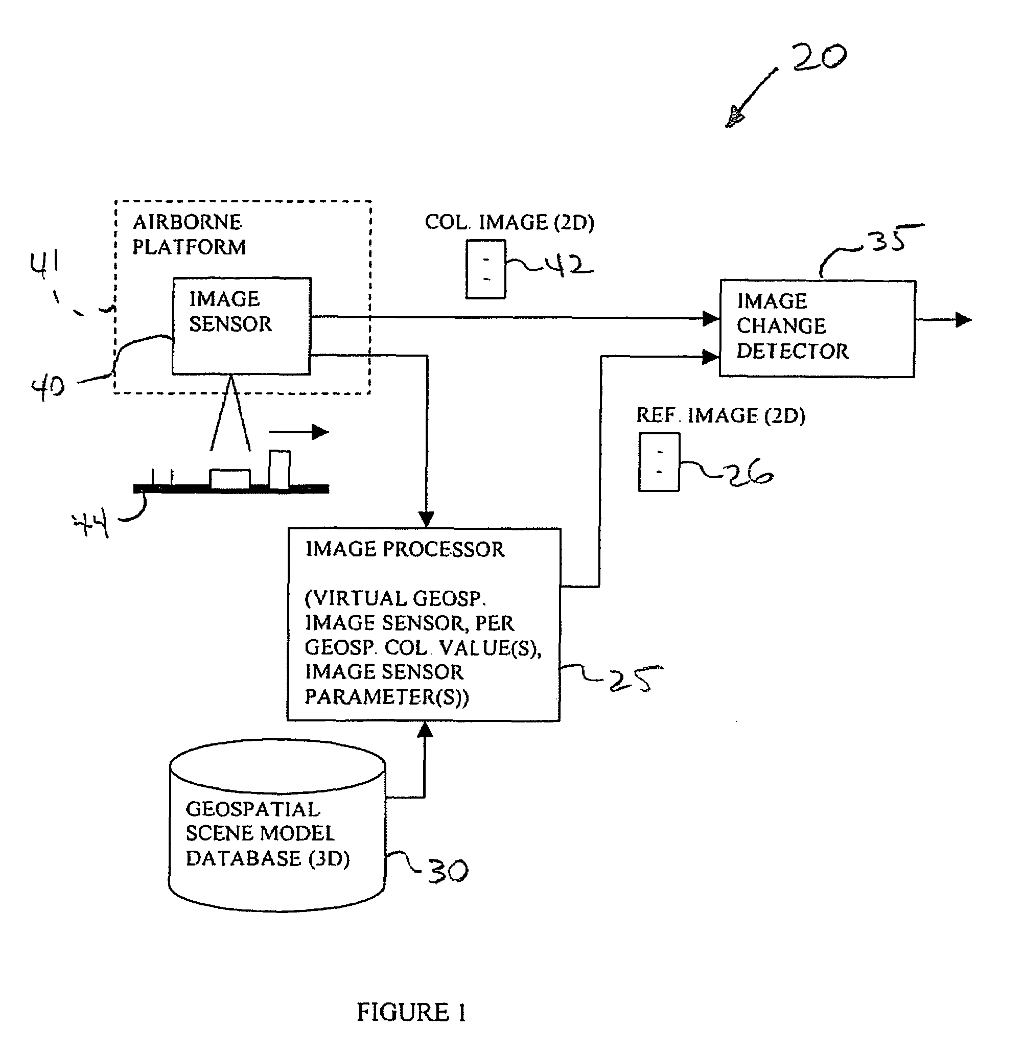
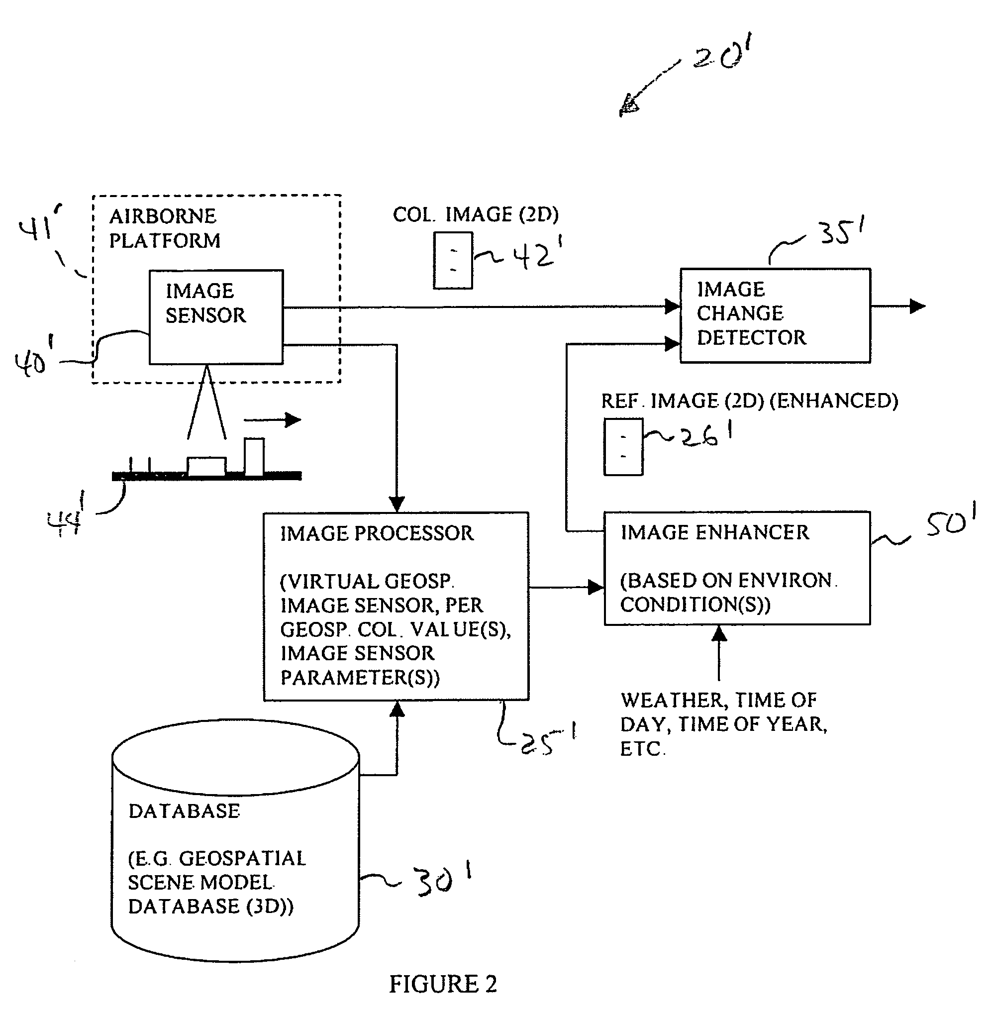
[0028]Referring initially to FIG. 1, an image change detecting system 20 is initially described. As shown in the illustrated embodiment, the image change detecting system 20 comprises an image processor 25 cooperating with a geospatial scene model database 30 for generating a reference geospatial image 26 corresponding to the collected geospatial image 42. The system 20 als...


PUM


Abstract

An image change detecting system may include an image processor cooperating with the database for generating a reference geospatial image corresponding to the collected geospatial image, an image enhancer for enhancing at least one of the reference geospatial image and the collected geospatial image based upon at least one environmental condition, and a change detector cooperating with the image processor and the image enhancer. The change detector may detect a change between the collected geospatial image and the reference geospatial image with at least one thereof enhanced by the image enhancer based upon the at least one environmental condition. The environmental condition may include a weather condition, a time of day, or a time of year. The environmental condition may be typically associated with the collected geospatial image.

Description

FIELD OF THE INVENTION[0001]The present invention relates to the field of image processing, and, more particularly, to geospatial image processing and related methods.BACKGROUND OF THE INVENTION[0002]As discussed in the background of U.S. Pat. No. 6,654,690 to Rahmes et al. and assigned to the assignee of the present invention, topographical models of geographical areas may be used for many applications. For example, topographical models may be used in flight simulators and for planning military missions. Furthermore, topographical models of man-made structures (e.g., cities) may be extremely helpful in applications such as cellular antenna placement, urban planning, disaster preparedness and analysis, and mapping, for example.[0003]Various types and methods for making topographical models are presently being used. One common topographical model is the digital elevation map (DEM). A DEM is a sampled matrix representation of a geographical area that may be generated in an automated f...

Claims


Application Information

Patent Timeline
Patent Type & Authority Patents(United States)
IPC IPC(8): G05D1/00G06K9/00G06K9/32G06T17/05
CPCG06T5/50G06T7/0002G06T2207/30181
Inventor GARCEAU, ROBERT M.RAHMES, MARKGUTIERREZ, GUILLERMO E.HAM, TODDNEMETHY, JOSEPHHACKETT, JAY
Owner HARRIS CORP
Why Eureka
Try Eureka